Control System Performance:
From the foregoing discussion on control systems it can be seen that the behaviour of the control systems can be specified, based on several time domain specifications. To provide a basis for comparison of several types of control and solution, the performance indices are defined. These help as a quantitative measure of the system performance in which the system specifications are emphasised. The practical requirements of a system can be dictated by these indices. One must be able to derive these indices from the requirements of the system and to determine them from experiments. In a linear Control System Performance indices are normally independent of the operating point. Sometimes a compromise may be required between the parameters. The design of the power circuit and control depends mainly on satisfying these performance indices.
The time domain specifications of a Control System Performance are normally defined from its transient response to different inputs. These are:
1.Steady state error: This is the deviation of the actual output from the desired one in the final steady state condition. For a step input, the output follows the input and hence the steady state error is the deviation of the output from the input. This is called offset Steady state error depends on gain in the case of proportional control. It is theoretically zero for integral control. For ramps and parabolic inputs velocity and acceleration errors defined.
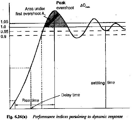
2.Rise time: The time period between the instants of the change in the input or disturbance and the output attaining the value of the input for the first time; x = 0 for the first instance for under damped systems. For overdamped systems this is the time period between the output values 10-90% of the input. This characterises the speed of response.
3.Peak time: The peak time is the time period between the instants of the change in the input or disturbance and the first peak overshoot of the
4.Settling time: The period of time which starts when the change in the input occurs and ends when the output differs from the input with an acceptable This is related to the time constant of the system.
5.Overshoot Mp of the controlled quantity. is the maximum deviation of the output from the desired one (input) during the control when the change in the input occurs. This is defined by
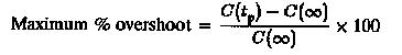
This is directly a measure of the relative stability of the system. It must be within 3 to 5%.
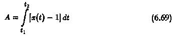
The quantity of the dynamic response which is specified by the above can be represented by the following performance indices (Fig. 6.26).
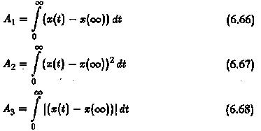
The first one is useful for representing a periodic behaviour, whereas the others are suitable for evaluating analog computer results. In the design of the required control the area under the first overshoot is considered and it is
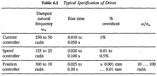
The comparison of several performance indices is made in Table 6.1. These are normally useful in the design of Control System Performance, to meet the required performance.
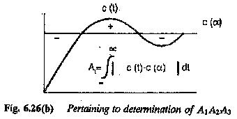
The frequency response is advantageously employed in the design of Control System Performance. A set of frequency domain specifications are also identified.
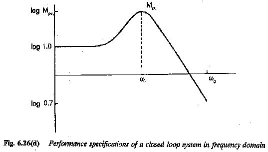
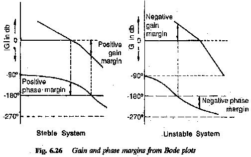
The speed of response of a control system is characterised by the gain cross-over frequency of the frequency response. The phase margin qualifies the overshoot of the system. Therefore the frequency response specifications are
1.The limiting frequency ωg at which the closed loop gain > 0.7.
2.The frequency ω0 where the amplitude attains peak value