Proportional Plus Integral Control:
Proportional Plus Integral Control – It is seen from the earlier discussion that with the speed governing system installed on each machine, the steady load frequency characteristic for a given speed changer setting has considerable droop, e.g. for the system being used for the illustration above, the steady state droop in frequency will be 2.9 Hz [see Eq. (8.23b)] from no load to full load (1 pu load).
![]()
System frequency specifications are rather stringent and, therefore, so much change in frequency cannot be tolerated. In fact, it is expected that the steady change in frequency will be zero. While steady state frequency can be brought back to the scheduled value by adjusting speed changer setting, the system could under go intolerable dynamic frequency changes with changes in load.
It leads to the natural suggestion that the speed changer setting be adjusted automatically by monitoring the frequency changes. For this purpose, a signal from Δf is fed through an integrator to the speed changer resulting in the block diagram configuration shown in Fig. 8.10. The system now modifies to a proportional plus integral controller, which, as is well known from control theory, gives zero steady state error, i.e. Δf Isteady state = 0.

The signal ΔPC(s) generated by the integral control must be of opposite sign to ΔF(s) which accounts for negative sign in the block for integral controller. Now
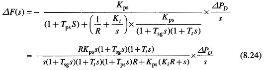
Obviously,
![]()

In contrast to Eq. (8.16) we find that the steady state change in frequency has been reduced to zero by the addition of the integral controller. This can be argued out physically as well. Δf reaches steady state (a constant value) only when ΔPC = ΔPD = constant. Because of the integrating action of the controller, this is only possible if Δf = 0.
In central load frequency control of a given control area, the change (error) in frequency is known as Area Control Error (ACE). The additional signal fed back in the modified control scheme presented above is the integral of ACE.
In the above scheme ACE being zero under steady conditions, a logical design criterion is the minimization of ∫ ACE dt for a step disturbance. This integral is indeed the time error of a synchronous electric clock run from the power supply. In fact, modern power systems keep track of integrated time error all the time. A corrective action (manual adjustment ΔPC , the speed changer setting) is taken by a large (preassigned) station in the area as soon as the time error exceeds a prescribed value.
Dynamic Response of Load Frequency Controller:
The dynamics of the proportional plus integral controller can be studied numerically only, the system being of fourth order—the order of the system has increased by one with the addition of the integral loop. The dynamic response of the proportional plus integral controller with Ki = 0.09 for a step load disturbance of 0.01 pu obtained through digital computer are plotted in Fig. 8.11. For the sake of comparison the dynamic response without integral control action is also plotted on the same figure.
