Trapatt Diode Construction and Working:
The Trapatt Diode Construction and Working is derived from and closely related to the IMPATT diode. Indeed, as pointed out near the beginning of this section, at first it was merely a different, “anomalous,” method of operating the IMPATT diode. A greatly simplified operation will now be described.
Basic Operation:
Consider an IMPATT diode mounted in a coaxial cavity, so arranged that there is a short circuit a half-wavelength away from the diode at the IMPATT operating frequency. When oscillations begin, most of the power will be reflected across the diode, and thus the RF field across it will be many times the normal value for IMPATT operation. This will rapidly cause the total voltage across the diode to rise well above the breakdown threshold value used in IMPATT operation. As avalanche now takes place, a plasma of electrons and holes is generated, placing a large potential across the junction, which opposes the applied dc voltage. The total voltage is thereby reduced, and the current pulse is trapped behind it. When this pulse travels across the n+ drift region of the semiconductor chip, the voltage across it is thus much lower than in IMPATT operation. This has two effects. The first is a much slower drift velocity, and consequently longer transit time, so that for a given thickness the operating frequency is several times lower than for corresponding IMPATT operation. The second point of great interest is that, when the current pulse does arrive at the cathode, the diode voltage is much lower than in an IMPATT diode. Thus dissipation is also much lower, and efficiency much higher. The operation is similar to class C, and indeed the Trapatt Diode Construction and Working lends itself to pulsed instead of CW operation.
Practical considerations:
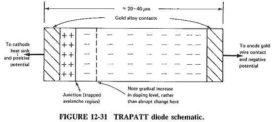
Although they were first proposed in the early 1970s, commercial Trapatt Diode Construction and Working diodes are only now becoming commercially available. They tend to be planar silicon diodes, with structures corresponding to those of IMPATT diodes but with gradual, rather than abrupt, changes in doping level between the junction and the anode. Furthermore, they are likely to use complementary n+ -p-p+ structures as shown in Figure 12-31, instead of the p+ -n-n+ IMPATT chip for reasons of better dissipation.
Because the drift velocity in a Trapatt Diode Construction and Working is much less than in an IMPATT diode, either operating frequencies must be lower or the active regions must be made thinner. In fact, both these considerations are borne out by results obtained. On the one hand, most good experimental TRAPATT results have been for frequencies under 10 GHz, and on the other hand, it has been found that by the time 5 GHz is reached, the width of the depletion layer is only 2 μm. Since the TRAPATT pulse is rich in harmonics, amplifiers or oscillators can be designed to tune to these harmonics, and operation above X band in this manner is possible.
Performance and Applications of Avalanche Diodes:
IMPATT diode performance:
Commercial diodes are currently produced over the frequency range from 4 to about 200 GHz, over which range the maximum output power per diode varies from nearly 20 W to about 50 mW. This means that, above about 20 GHz, the IMPATT diode produces a higher CW power output per unit than any other semiconductor device. Typical efficiency is about 10-20 percent up to 40 GHz, reducing to 1 percent as frequency is raised to 200 GHz. Several diodes outputs may be combined, giving a significantly greater output. Pulsed powers are generally one magnitude higher. Note that the above figures, for the most part, are for single-drift diodes.
Laboratory devices have produced as much as 30 W CW at 12 GHz, 300 mW at 140 GHz and 75 mW at 220 GHz, with one laboratory reporting 1 mW CW at over 300 GHz. Pulsed powers similarly range from about 50 W at 10 GHz to 3 W at 140 GHz. However, experimental results should be taken with a grain of salt. What is often reported is the best result obtained from several specially made diodes. What is often not reported is that maximum efficiency need not coincide with maximum output power or that a diode died of thermal runaway soon after the experiment. It should be noted that results being currently obtained from double-drift IMPATT diodes augur well for the device, especially as regards efficiency, for which figures in excess of 20 percent are being consistently reported, together with higher powers at the highest frequencies.
The biggest problem of IMPATT operation is noise. Avalanche is a very noisy process, and the high operating current helps the generation of shot noise. Thus IMPATT diode oscillators are not as good as either klystrons or Gunn diodes for spurious AM or FM noise, by quite a significant margin. When used as amplifiers, IMPATT diodes produce noise figures of the order of 30 dB, not as good as TWT amplifiers.
IMPATT oscillators and amplifiers:
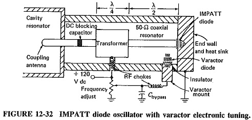
The dynamic impedance of an IMPATT diode is -10 Ω in parallel with 1 pF, as a good approximation. Like the Gunn diode, therefore, it has a negative resistance which must be placed in a low-impedance environment. Figure 12-32 shows a suitable arrangement. The IMPATT diode is located at the end of the center conductor in a low-impedance coaxial resonator, and a quarter-wave transformer is used to step up the impedance seen at its point of connection. Oscillations are basically at the frequency at which the length of the coaxial resonator is a half-wave, but this is influenced by the capacitance of the varactor diode. This diode is used for tuning, with its capacitance varied by a change in the applied bias. Frequency modulation could be achieved in exactly the same manner. Typical frequency variation is a few hundred megahertz at 10 GHz. Because of their close dependence on transit time through the entire drift space, IMPATT diodes do not lend themselves to tuning over nearly as wide a frequency range as Gunn diodes. Consequently YIG tuning is not used, since varactors match IMPATTs in that regard.
IMPATT diode amplifiers are available with outputs similar to those of oscillators at about the same frequency range. They are comparable to Gunn diode amplifiers in that they also require circulators, but efficiencies for Gunn amplifiers (up to 10 percent) and power outputs are much higher. Gain is similarly 6 to 10 dB per stage, and bandwidths are up to about 10 percent of the center frequency. Higher frequencies of operation, to over 100 GHz, are another attraction, but noise is still a problem.
Performance of TRAPATT oscillators and amplifiers:
As was explained in a preceding section, Trapatt Diode Construction and Working requires a large RF voltage swing, the kind unlikely to be obtained from switching transients. It seems that TRAPATT oscillators most probably start in the IMPATT mode, then switch over when oscillations have built up sufficiently. The circuit must thus be arranged to permit this to happen. However, no such difficulties are encountered with TRAPATT amplifiers, where an adequately large signal is present, being the input. Another practical point which must be taken into account is the extreme TRAPATT sensitivity to harmonics. Thus, when operating in the fundamental mode, care must be taken to ensure that the second, third and even fourth harmonics cannot be maintained in the tuned circuit.
Most TRAPATT oscillators and amplifiers are still in the laboratory stage. However, such impressive results have been obtained that it should not be long before units are available commercially, now that the initial difficulties in establishing and maintaining coherent oscillations seem to have been overcome. With typical duty cycles of the order of 0.1 percent, pulsed powers as high as 200 W at 3 GHz have been produced, with efficiencies in excess of 30 percent. At about 1 GHz, pulsed output powers of 600 W and (independently) an efficiency of 75 percent have been obtained. These figures are for oscillators, but amplifier figures should be comparable. Performance above X band is not very impressive, because of the mode of operation. It should be mentioned that many microwave operations take place at X band or below.