Antenna Definition:
The Antenna Definition is a quick review of impedance matching (basic transformer theory) and resonant circuits. It was pointed out that maximum power transfer could be achieved only when the source matched the load. The antenna must have the ability to match the transmission line (source impedance Ω, coax 300-Ω twin lead) and the load (the atmosphere, 377 Ω). At radio frequencies, and depending on physical length, a wire can be an impedance-matching device.
The Antenna Definition also must act somewhat as a resonant circuit; i.e., it must have the ability to transfer energy alternately from electrostatic to electromagnetic. If the Z match is correct, the energy being transferred will radiate energy into the atmosphere in the same way a transformer transforms energy from primary to secondary. This discussion is an oversimplification of the process encountered in RF transmission but can serve as a visual basis for further discussion (see Figure 9-1).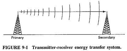
An antenna is a structure that is generally a metallic object, often a wire or group of wires, used to convert high-frequency current into electromagnetic waves, and vice versa. Apart from their different functions, transmitting and receiving antennas have similar characteristics, which means that their behavior is reciprocal.
The spacing, length, and shape of the device are related to the wavelength λ of the desired transmitter frequency; i.e., mechanical length is inversely proportional to the numerical value of the frequency.
![]()
where
T = time
f = frequency
![]()
Therefore, for an antenna operating at 50 MHz, t = 1/f = 0.02 μs = 6 m, and wavelength = 300 m x time μs = c/f = 3 x 10⁸/f.
Electromagnetic Radiation:
When RF energy is fed into a mismatched transmission line, standing waves occur. Energy is lost or radiated into the space surrounding the line. This process is considered unwanted in the transfer of energy to the radiation device. If we examine this process and expand upon it (Figure 9-2a), we can see, by separating the ends of the transmission line, that more surface area of the wire is exposed to the atmosphere and enhances the radiation process.
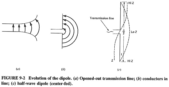
The radiation efficiency of this system is improved even more when the two wires are bent at 90° (right angles) to each other (Figure 9-2b). The electric and magnetic fields are now fully coupled to the surrounding space instead of being confined between the two wires, and maximum radiation results. This type of radiator is called a dipole. When the total length of the two wires is a half wavelength, the Antenna Definition is called a half-wave dipole.
This configuration has similar characteristics to its equivalent length transmission line (1/4 λ). It results in high impedance (Hi Z) at the far ends reflected as low impedance (Lo Z) at the end connected to the transmission line. This causes the antenna to have a large current node at the center and large voltage nodes at the ends, resulting in maximum radiation.
The Elementary Doublet (Hertzian Dipole):
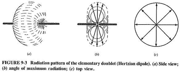
The doublet is a theoretical antenna shorter than a wavelength (Figure 9-3a). It is used as a standard to which all other antenna characteristics can be compared.
The field strength of this antenna can be calculated as follows:
![]()
Where
E = magnitude of field strength (μs/m)
r = distance
Le = antenna length
I = current amplitude
θ = the angle of the axis of the wire and the point of maximum radiation
As shown in Figure 9-36, the radiation is a double circular pattern, with maximum radiation at 90° to the axis of the wire.