Parabolic Antenna:
The Parabolic Antenna is a plane curve, defined as the locus of a point which moves so that its distance from another point (called the focus) plus its distance from a straight line (directrix) is constant. These geometric properties yield an excellent microwave or light reflector, as will be seen.
Geometry of the parabola:
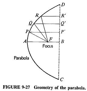
Figure 9-27 shows a parabola CAD whose focus is at F and whose axis is AB. It follows from the definition of the parabola that
![]()
where
k = a constant, which may be changed if a different shape of parabola is required
AF = focal length of the parabola
Note that the ratio of the focal length to the mouth diameter (AF/CD) is called the aperture of the parabola, just as in camera lenses.
Consider a source of radiation placed at the focus. All waves coming from the source and reflected by the parabola will have traveled the same distance by the time they reach the directrix, no matter from what point on the parabola they are reflected. All such waves will be in phase. As a result, radiation is very strong and concentrated along the AB axis, but cancellation will take place in any other direction, because of path-length differences. The parabola is seen to have properties that lead to the production of concentrated beams of radiation.
A practical reflector employing the properties of the parabola will be a three-dimensional bowl-shaped surface, obtained by revolving the parabola about the axis AB. The resulting geometric surface is the paraboloid, often called a Parabolic Antenna reflector or microwave dish. When it is used for reception, exactly the same behavior is manifested, so that this is also a high-gain receiving directional antenna reflector. Such behavior is, of course, predicted by the principle of reciprocity, which states that the properties of an Parabolic Antenna are independent of whether it is used for transmission or reception. The reflector is directional for reception because only the rays arriving from the BA direction, i.e., normal to the directrix, are brought together at the focus. On the other hand, rays from any other direction are canceled at that point, again owing to path-length differences. The reflector provides a high gain because, like the mirror of a reflecting telescope, it collects radiation from a large area and concentrates it all at the focal point.
Properties of paraboloid reflectors:
The directional pattern of an Parabolic Antenna using a paraboloid reflector has a very sharp main lobe, surrounded by a number of minor lobes which are much smaller. The three-dimensional shape of the main lobe is like that of a fat cigar (Figure 9-27), in the direction AB. If the primary, or feed, antenna is nondirectional, then the paraboloid will produce a beam of radiation whose width is given by the formulas.
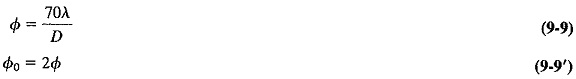
where
λ = wavelength, m
Φ = beamwidth between half-power points, degrees
Φ0 = beamwidth between nulls, degrees
D = mouth diameter, m
Both equations are simplified versions of morecomplex ones, but they apply accurately to large apertures, that is, large ratios of mouth diameter to wavelength. They are thus accurate for small beamwidths. Although Equation (9-9′) is fairly universal, Equation (9-9) contains a restriction. It applies in the specific, but common, case of illumination which falls away uniformly from the center to the edges of the paraboloid reflector. This decrease away from the center is such that power density at the edges of the reflector is 10 dB down on the power density at its center.
There are two reasons for such a decrease in illumination:
(1) No primary antenna can be truly isotropic, so that some reduction in power density at the edges must be accepted.
(2) Such a uniform decrease in illumination has the beneficial effect of reducing the strength of minor lobes.
Note that the whole area of the reflector is illuminated, despite the decrease toward the edges. If only half the area of the reflector were illuminated, the reflector might as well have been only half the size in the first place.
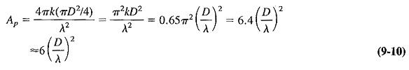
The gain of an antenna using a paraboloid reflector is influenced by the aperture ratio (D/A) and the uniformity (or otherwise) of the illumination. If the Parabolic Antenna is lossless, and its illumination falls away to the edges as previously discussed, then the power gain, as a good approximation, is given by
![]()
where
Ap = directivity (with respect to isotropic antenna)
GP = power gain if antenna is lossless
D = mouth diameter of reflector, m
Feed mechanisms:
The primary Parabolic Antenna is placed at the focus of the paraboloid for best results in transmission or reception. The direct radiation from the feed, which is not reflected by the paraboloid, tends to spread out in all directions and hence partially spoils the directivity. Several methods are used to prevent this, one of them being the provision of a small spherical reflector, as shown in Figure 9-28, to redirect all such radiation back to the paraboloid. Another method is to use a small dipole array at the focus, such as a Yagi-Uda or an end-fire array, pointing at the paraboloid reflector.
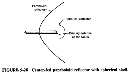
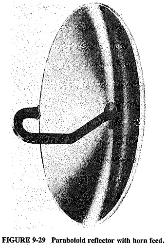
Figure 9-29 shows yet another way of dealing with the problem. A horn antenna (to be discussed in Section 9-7.2) pointing at the main reflector. It has a mildly directional pattern, in the direction in which its mouth points. Direct radiation from the feed antenna is once again avoided. It should be mentioned at this point that, although the feed antenna and its reflector obstruct a certain amount of reflection from the paraboloid when they are placed at its focus, this obstruction is slight indeed.
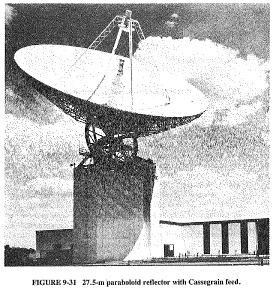
Another feed method, the Cassegrain feed, is named after an early-eighteenth-century astronomer and is adopted directly from astronomical reflecting telescopes; it is illustrated in Figures 9-30 and 9-31. It uses a hyperboloid secondary reflector.
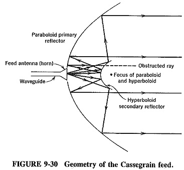
One of its foci coincides with the focus of the paraboloid, resulting in the action shown (for transmission) in Figure 9-30. The rays emitted from the feed horn antenna are reflected from the paraboloid mirror. The effect on the main paraboloid reflector being the same as that of a feed antenna at the focus. The main reflector then collimates (renders parallel) the rays in the usual manner.
The Cassegrain feed is used when it is desired to place the primary antenna in a convenient position and to shorten the length of the transmission line or waveguide connecting the receiver (or transmitter) to the primary. This requirement often applies to low-noise receivers, in which the losses in the line or waveguide may not be tolerated, especially over lengths which may exceed 30 m in large antennas. Another solution to the problem is to place the active part of the transmitter or receiver at the focus. With transmitters this can almost never be done because of their size, and it may also be difficult to place the RF amplifier of the receiver there. This is either because of its size or because of the need for cooling apparatus for very low-noise applications (in which case the RF amplifier may be small enough, but the ancillary equipment is not). Such placement of the RF amplifier causes servicing and replacement difficulties, and the Cassegrain feed is often the best solution.
As shown in Figure 9-30, an obvious difficulty results from the use of a secondary reflector, namely, the obstruction of some of the radiation from the main reflector. This is a problem, especially with small reflectors, because the dimensions of the hyperboloid are determined by its distance from the horn primary feed and the mouth diameter of the horn itself, which is governed by the frequency used. One of the ways of overcoming this obstruction is by means of a large primary reflector (which is not always economical or desirable), together with a horn placed as close to the subreflector as possible. This is shown in Figure 9-31 and has the effect of reducing the required diameter of the secondary reflector. Vertically polarized waves are emitted by the feed, are reflected back to the main mirror by a hyperboloid consisting of vertical bars and have their polarization twisted by 90∘ by a mechanism at the paraboloid. The reflected waves are now horizontally polarized and pass the vertical bars of the secondary minor.
Other Parabolic Antenna reflectors:
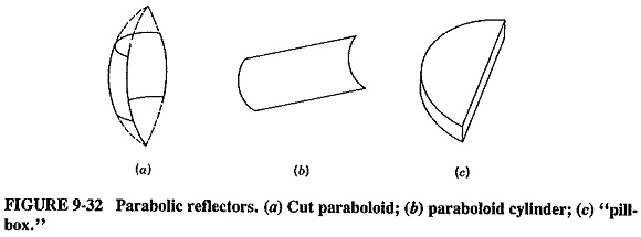
The full paraboloid is not the only practical reflector that utilizes the properties of the parabola. Several others exist, and three of the most common are illustrated in Figure 9-32. Each of them has an advantage over the full paraboloid in that it is much smaller, but in each instance the price paid is that the beam is not as directional in one of the planes as that of the paraboloid. With the pillbox reflector, the beam is very narrow horizontally, but not nearly so directional vertically. First appearances might indicate that this is a very serious disadvantage, but there are a number of applications where it does not matter in the least. In ship-to-ship radar, for instance, azimuth directivity must be excellent, but elevation selectivity is immaterial another ship is bound to be on the surface of the ocean!
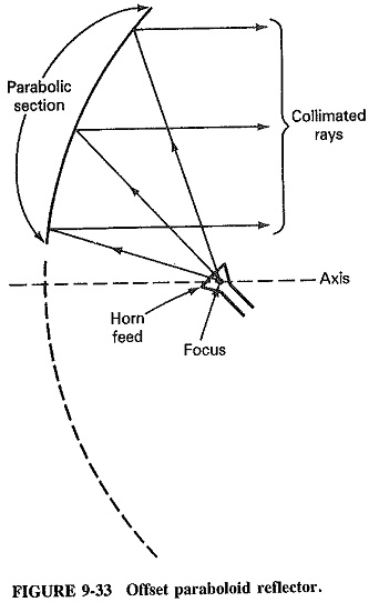
Another form of the cut paraboloid is shown in Figure 9-33, in cross section. This is the offset paraboloid reflector, in which the focus is located outside the aperture (just below it, in this case). If an antenna feed is now placed at the focus, the reflected and collimated rays will pass harmlessly above it, removing any interference. This method is often used if, for some reason, the feed antenna is rather large compared with the reflector.
Shortcomings and difficulties:
The beam from an antenna with a paraboloid reflector should be a narrow beam, but in practice contains side lobes. These have several unpleasant effects. One is the presence of false echoes in radar, due to reflections from the direction of side lobes (particularly from nearby objects). Another problem is the increase in noise at the antenna terminals, caused by reception from sources in a direction other than the main one. This can be quite a nuisance in low-noise receiving systems, e.g., radioastronomy. .
There are a number of causes for this behavior, the first and most obvious being imperfections in the reflector itself. Deviations from a true paraboloidal shape should not exceed one-sixteenth of a wavelength. Such tolerances may be difficult to achieve in large dishes whose surface is a network of wires rather than a smooth, continuous skin. A mesh surface is often used to reduce wind loading on the antenna and extra strain on the supports and also to reduce surface distortion caused by uneven wind force distribution over the surface. Such surface strains and distortion cannot be eliminated completely and will occur as a large dish is pointed in different directions.
Diffraction is another cause of side lobes and will occur around the edges of the paraboloid, producing interference as described in the preceding chapter, This is the reason for having reflectors with a mouth diameter preferably in excess of 10 wave-lengths. Some diffraction may also be caused by the waveguide horn support, as in Figure 9-29, or the quadripod supports of the secondary reflector in Figure 9-31.
The finite size of the primary antenna also influences the beamwidth of antennas using paraboloid reflectors. Not being a true point source, the feed antenna cannot all be located at the focus. Defects known as aberrations are therefore produced. The main lobe is broadened and side lobes are reinforced. Increasing the aperture of the reflector, so that the focal length is about one-quarter of the mouth diameter, is of some help here. So is the use of a Cassegrain feed, which partially helps to concentrate the radiation of the feed antenna to a point.
The fact that the primary antenna does not radiate evenly at the reflector will also introduce distortion. If the primary is a dipole, it will radiate more in one plane than the other, and so the beam from the reflector will be somewhat flattened. This may be avoided by the use of a circular horn as the primary, but difficulties arise even hex. This is because the complete surface of the paraboloid is not uniformly illuminated, since there is a gradual tapering of illumination toward the edges, which was mentioned in connection with Equation (9-10). This has the effect of giving the antenna a virtual area that is smaller than the real area and leads, in the case of receiving antennas, to the use of the term capture area. This is the effective receiving area of the Parabolic Antenna reflector and may be calculated from the power received and its comparison with the power density of the signal being received. The result is the area of a fully and evenly illuminated paraboloid required to produce that signal power at the primary. The capture area is simply related to the actual mouth area by the expression
![]()
where
A0 = capture area
A = actual area
k = constant depending on the antenna type and configuration = 0.65 (approximately) for a paraboloid fed by a half-wave dipole
Equation (9-11) may be used to indicate how Equation (9-10) is derived from a more fundamental relation,
![]()
Substituting for the area of the paraboloid mouth, we have