Resistance Welding Machines – Overview and Circuit Diagram:
Resistance welding machines incorporates a transformer, suitable electrodes for supplying current to the weld and arrangement for controlling the mechanical pressure, and finally, means for controlling the duration of weld current flow. The mechanical pressure may he exerted through levers and clutch by an electric motor or by compressed air. The magnitude of pressure required depends upon the type of work and may vary from a few kg for thin sheets or wires up to a tonne or more for heavy work.
In the older type of Resistance welding machines, the electrodes were brought on to the work and the electrical circuit closed by the operation of a pedal. Thus application of pressure and the time duration of current flow used to be controlled by the operator and for this operator needs to he experienced and skilled. The modern practice is to pass heavy currents for shorter time durations (ranging from 10 ms to 100 ms). The equipment used for this purpose may be constant time, current-actuated, or energy-actuated types.
Constant time equipment is employed in high speed production where the work has a consistently clean surface. Constant time equipment may be provided with mechanical control or electrical control. In mechanical control providing up to 300 welds per minute, the device employed is a cam-operated switch, connected in the primary circuit of a welding transformer, driven from the resistance welding machines. For a large number of welds per minute the mechanical arrangement becomes unsuitable because it is not capable of providing consistently accurate timing, due to wear of the cam and operating mechanism, arcing and burning of the contacts and irregularities caused by closing of switch at different instants in the cycle.
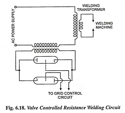
An alternative arrangement is to control the timing through grid controlled ignitrons or thyratrons. It is easier to build tubes for a high voltage and small current than with a low voltage and high current. An arrangement using valves in the secondary circuit of a series transformer is shown in Fig. 6.18. When the tubes conduct, the series transformer secondary is almost short-circuited, and whole of the supply voltage is available across the welding transformer primary. But when the tubes are not conducting, the series transformer primary winding offers a high impedance in the circuit of the welding transformer and the current is reduced to a negligible value. Auxiliary valves are employed for controlling the timing of the negative potential applied to the grids of the main tubes.
Constant-time method of control does not yield consistently good results when there may be variations in the conditions under which successive welds are made, due to variations in supply voltage or mechanical pressure, wearing of electrodes, surface irregularities etc. The energy-actuated control, wherein definite amount of energy is supplied to the weld, is used, Constant-time method of control did not prove to be successful, particularly with modern high-speed welding. The energy-actuated control, which permits the current to flow until a predetermined amount of energy has been supplied to the weld, is theoretically an ideal method. However, the control equipment is quite complicated.