Medium Transmission Line Voltage:
In short transmission line calculations; the effects attic line capacitance are neglected because such lines have smaller lengths and transmit power at relatively low voltages (<20 kV): However, as the length and voltage of the line increase, the capacitance gradually becomes of greater importance. Since Medium Transmission Line Voltage have sufficient length (50-150 km) and usually operate at voltages greater than 20 kV, the effects of Capacitance cannot be neglected. Therefore, in order to obtain reasonable accuracy in Medium Transmission Line Voltage calculations, the line capacitance must be taken into consideration.
The capacitance is uniformly distributed over the entire length of the line. However, in order to !make the calculations simple, the lute capacitance is assumed to be lumped or concentrated in the form of capacitors shunted across the tine at one or more points. Such a treatment of localizing the line capacitance gives reasonably accurate results. The most commonly used methods (known as localized capacitance methods)for the Solution of Medium Transmission lines are:
- End Condenser Method
- Nominal T Method
- Nominal π Method
Although the above methods are used for obtaining the performance calculations of Medium Transmission Line Voltage, they can also be used for short lines if their line capacitance is given in a particular problem.
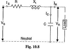
End Condenser Method
In this method, the capacitance of the line is lumped or concentrated at the receiving or load end as shown in Fig. 10.8. This method of localizing the line capacitance at the load end overestimates the effects of capacitance. In Fig. 10.8, one phase of the 3-phase transmission line is shown as it is more convenient to work in phase instead of line-to-line values.
Let
IR = load current per phase
R = resistance per phase
XL = inductive reactance per phase
C = capacitance per phase
cos ΦR = receiving end power factor (lagging)
VS = sending end voltage per phase
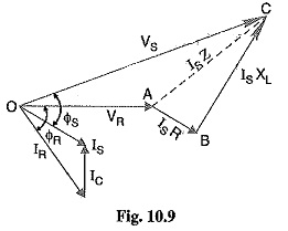
The phasor diagram for the circuit is shown in Fig 10.9. Taking the receiving end voltage VR as the reference phasor,
we have,
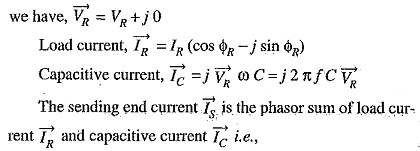
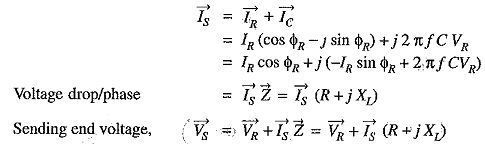
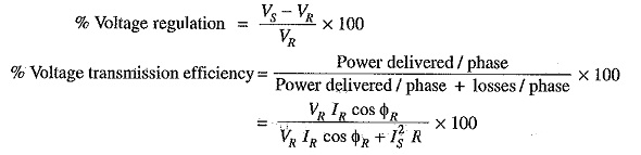
Thus, the magnitude of sending end voltage VS can be calculated.
Limitations:
Although end condenser method for the solution of Medium Transmission Line Voltage is, simple to work out calculations, yet it has the following drawbacks.:
- There is a considerable error (about 10%) in calculations because the distributed capacitance has been assumed to be lumped ors concentrated.
- This method overestimates the effects of line capacitance.
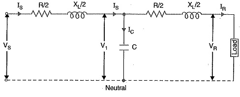
Nominal T Method
In this method, the whole line capacitance is assumed to be concentrated at the middle point of the line and half the line resistance and reactance are lumped on its either side as shown in Fig. 10.11. Therefore, in this arrangement, full charging current flows over half the line. In Fig. 10.11, one phase of 3-phase transmission line is shown as it is advantageous to work in phase instead of line-to-line values.
Let
IR = load current per phase
R = resistance per phase
XL= inductive reactance per phase
C = capacitance per phase
cos ΦR = receiving end power factor (lagging)
VS= sending end voltage/phase
V1 = voltage across capacitor C
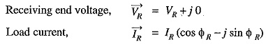
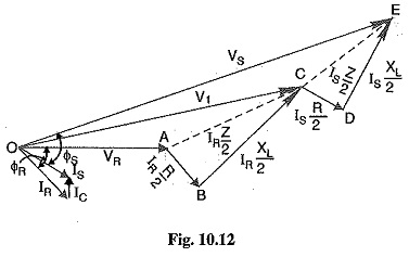
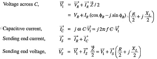
The phasor diagram for the circuit is shown in Fig. 10.12. Taking the receiving end voltage VR as the reference phasor, we have,
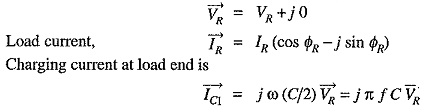
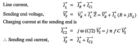
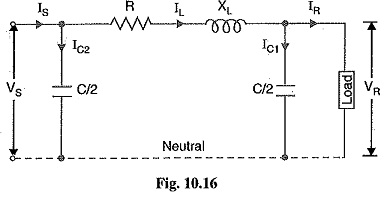
Nominal π Method
In this method, capacitance of each conductor (i.e., line to neutral) is divided into two halves; one half being lumped at the sending end and the other half at the receiving end as shown in Fig. 10.16. It is obvious that capacitance at the sending end has no effect on the line drop. However, its charging current must be added to line current in order to obtain the total sending end current.
Let
IR = load current per phase
R = resistance per phase
XL = inductive reactance per phase
C = capacitance per phase
cos ΦR = receiving end power factor (lagging)
VS = sending end voltage per phase
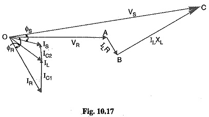
The phasor diagram for the circuit is shown in Fig. 10.17. Taking the receiving end voltage as the reference phasor, we have,