Digital Data Recording System:
Digital Data Recording – Digital magnetic tapes are often used as storage devices in digital data processing applications. Digital tape units are of two types, incremental and synchronous.
Incremental digital recorders are commanded to step ahead (increment) for each digital character to be recorded. Input data may be at a relatively slow, or even discontinuous rate. In this way, each character is equally and precisely spaced along the tape.
In a synchronous digital recorder, the tape moves at a constant speed (about 75 cm/s) while a large number of data characters are recorded. The data inputs are at precise rates, up to tens of thousands of characters per second. The tape is rapidly brought up to speed, recording takes place, and the tape is brought to a fast stop. In this way a block of characters (a record) is written with each character spaced equally along the tape. Blocks of data are usually separated from each other by an erased area on the tape called the record gap. The synchronous tape unit starts and stops the tape for each block of data to be recorded.
Characters are represented on magnetic tape by a coded combination of 1-bit in appropriate tracks across the tape width. The recording technique used in most instrumentation tape recorders is the industry accepted IBM format of Non-Return Zero (NRZ) recording.
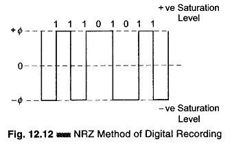
In this system the tape is magnetically saturated at all times in either the positive or the negative direction. The NRZ method uses the change in flux direction on the tape to indicate 1 bit, and no change in flux direction to indicate 0 bit. This method is illustrated in Fig. 12.12, where the binary number 11101011 is represented by a flux pattern in the NRZ system. The simplest method of coding the recording head field is to reverse its direction.
In digital data recording, a recording field of amplitude sufficient to produce magnetic saturation through the complete tape layer thickness is reversed to record a 1 signal and kept constant to record a 0 signal.
Reproduction of this recording is achieved by using a timing signal obtained from a separate clock track, corresponding to the time when a 1 or 0 is recorded.
Self-clocking systems, where the recording field is reversed at regular intervals and 1 or 0 signals are recorded between these clock signals, are also used.
It is evident that the highest resolution is obtained in NRZ recording by adjusting the field amplitude, so that maximum longitudinal decrement occurs in the surface layer of the tape. In practice, larger fields are usually employed to ensure more reliable recordings on a coated thicker tape. To minimize the effects of dropouts, large recording fields are used and resolution is sacrificed for increased reliability.
Present high density data recording on oxide powder tape is in the range of 1500 – 2000 flux reversals per inch. (By using thin metallic coatings with high coercive force, extensions up to 10000 reversals per inch are possible in future.)
Since magnetisation is independent of frequency and amplitude but relies only on the polarity of the recording current, the usual problems of non-linearity and distortion found in direct and FM recordings do not exist. The write coils of the tape head require only sufficient current, of the correct polarity, to saturate the tape. Two of the problems encountered in digital recording are signal drop out and spurious pulses (losing or adding data). Signal dropout or loss of pulses becomes serious when the packing density increases (a large number of bits per unit tape length).
As a check on dropout errors, most tape systems include a parity check. This check involves keeping track of the number of 1 bits of information initially recorded on the tape by writing a parity check pulse on an extra tape track. If the number of 1’s recorded is even it is called an even parity check, and if the number of 1’s recorded is odd, then it is an odd parity check. When a dropout occurs, the parity check does not agree with the actual recorded data and a parity error is detected.
Some systems use the parity error system to insert missing bits in the appropriate places in addition to indicating that a parity error has occurred.
Another scheme, called bipolar or alternate mark inversion, is illustrated in Fig. 12.13.
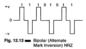
This format has no residual dc component and has zero power in the spectrum at zero frequency, as shown in Fig. 12.13. These are pulses of 50% duty cycle (they are only half as wide as the pulse interval allows) and by inverting the polarity of alternate 1 bits. The bipolar format is really a three state signal (+ V, 0, – V).
Advantages of Digital Data Recording:
- High accuracy.
- Insensitivity to tape speed.
- Use of simple conditioning equipment.
- The information is fed directly to a digital computer for processing and
Disadvantages of Digital Data Recording:
- Poor tape economy.
- The information from transducers is in analog form, hence an A/D converter is required.
- A high quality tape and tape transport mechanism are required.