Voltage Drop on Load and Regulation:
The change of average Voltage Drop on Load from the no load theoretical value expressed as a percentage of no load voltage is called the Regulation. The change in voltage (i.e.) the voltage drop ΔV is caused due to the ripple δV, and the capacitors not getting charged to the full voltage Vm when they are supplying the load current I1.
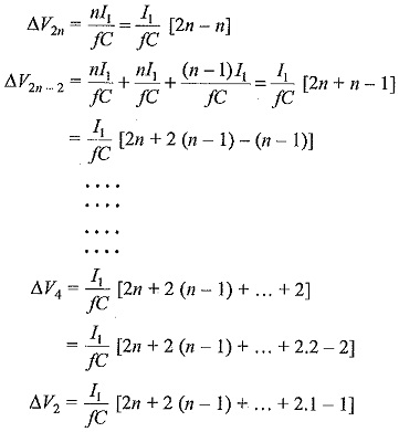
The Voltage Drop on Load condition ΔV is found by assuming that all the capacitors are of equal value ‘C’. It is seen from the analysis of ripple that all the capacitors are not charged to 2Vmax. The capacitor C2n is charged to (2Vmax – n I1/fC) only instead of 2Vmax because the charge given through C2n-1 in one cycle is equal to a voltage drop of n I1/fC. This is because, in each stage the loss of charge equal to a voltage drop of I1/fC to the load. In a similar manner the capacitor C2n-2 is charged to only [2Vmax – n I1/fC – n I1/fC – (n-1) I1/fC] since the reduction in voltage at this stage is further equal to n I1/fC at the capacitor C2n-1 and (n – 1) I1/fC at capacitor C2n-2. Thus, if the voltage drops at each of the capacitor C2n,C2n-2 etc. to C2 are designated as ΔV2n,ΔV2n-2,…ΔV2, the total voltage drop will be
Summing up all the voltage drops
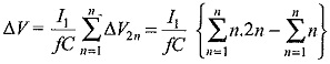
It is seen from Eq. (6.3) that most of the voltage drop is at the lowest stage capacitors C1,C2,C3,C4, etc. Hence it is advantageous to increase their values to be proportional to the stage number counted from the top. In other words C1C2 may be chosen as nC,C3C4 as (n – 1)C, etc.
For large values of n ( ≥ 5),n2/2 and n/6 terms in Eq. (6.3) will become small compared to 2/3 n3 and may be neglected; then the optimum number of stages for the minimum voltage drop may be expressed as
![]()
where I is the load current.
Thus, for a multiplier or a cascaded circuit with f = 50 Hz, C = 0.1 μF, Vmax = 100 kV and I = 5 mA, the number of stages n ≈ 10.
The regulation can be improved by increasing f, but an upper limit is set by the high voltage appearing across the inductances and high capacitor currents which are considerable. At present, the Cockcroft-Walton type voltage multipliers are available using selenium rectifiers and a.c. supply frequencies of 500 to 1000 Hz for output voltages of more than one million volts and load currents of 30 mA.
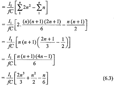
The voltage multiplier described in Sec. 6.1.3 is a single pulse voltage multiplier since it has only one rectified wave or pulse per cycle. Hence its ripple content is high. In order reduce the ripple as well as regulation and to improve the efficiency and power output, two or more pulse units per cycle are preferred. Single or three phase bridge is used as the basic rectifier or stage and the multiplier circuit is built in the same manner as that of the Cockcroft. Walton multiplier.
The arrangement for single phase two pulse and three phase six pulse circuits are shown in Figs 6.4(f) and 6.4 (g) respectively.
Single Phase Two Pulse Cascade Multiplier:
The basic voltage doubler unit consisting of D1,D2,C1,C2 is replaced by the bridge circuit D1,D2,D′1,D′2 with an extra capacitor C′1.. The centre tap of the supply transformer is connected to the junction of rectifiers D1,D2. The arrangement is simply an addition of another voltage doubler circuit D′1,D′2,C′1,C′2 along with the transformer OH2 for the negative cycle rectification.
The multiplier circuit is built for both positive and negative cycle rectification and the arrangement is called Symmetrical Cascade Unit. The ripple for this arrangement is nI/2fC as against n(n + 1)I/2fC with all capacitors of value equal to C and the regulation is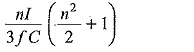
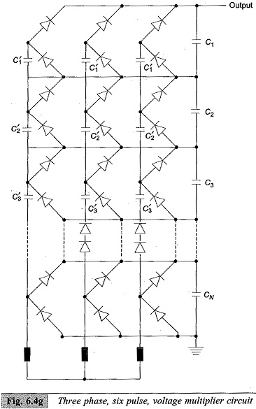
Three Phase Six Pulse Arrangement:
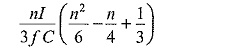
The three phase six pulse arrangement is a 3 phase bridge or Gratz circuit cascaded into a multiplier unit as shown in Fig. 6.4(f). Two more multiplier units for the other two phases of the three phase supply are connected in parallel to build this circuit. The ripple in this case is reduced to nI/6fC and regulation to
The two pulse circuit requires double the number of diodes and one and a half times the capacitors required for single pulse circuits. The six pulse circuit requires twice the number of diodes and capacitors used in single pulse circuit reduced and requirements needed in the specifications of D.C. test sources are easily met with much smaller ratings for the capacitors. Further, large currents required for pollution testing can be obtained only with three phase six pulse arrangement.