Autotransformer | Definition | Use of Auto transformer:
So far two-winding transformers have been discussed wherein the windings are electrically isolated. When the primary and secondary windings are electrically connected so that a part of the winding is common to the two as shown in Fig. 3.35 (core is not shown here), the transformer is known as an Autotransformer. Such a transformer is particularly economical where the voltage ratio is less than 2 in which case electrical isolation of the two windings is not essential.
The major applications are induction motor starters, interconnection of HV systems at voltage levels with ratio less than 2, and in obtaining variable voltage power supplies (low voltage and current levels). The autotransformer has lower reactance, lower losses, smaller exciting current and better voltage regulation compared to its two-winding counterpart. All this is on account of the fact that in an Autotransformer a part of the energy transfer is through the conduction process.

Figure 3.35 shows a single-phase Autotransformer having N1 turns primary with N2 turns tapped for a lower voltage secondary. The winding section BC of N2 turns is common to both primary and secondary circuits. In fact it is nothing but a conventional two-winding transformer connected in a special way. The winding section AB must be provided with extra insulation, being at higher voltage.
It will be assumed here that the magnetizing current is negligible; but it can easily be determined by a no-load test and accounted for.
With reference to Fig. 3.35 the two-winding voltage and turn-ratio is

As an autotransformer its voltage and turn-ratio is
![]()
It is easy to see that Eqs. (3.68) and (3.69) are related as
![]()
Visualizing that in Fig. 3.35 a two-winding transformer is connected as an Auto Transformer, let us compare the VA ratings of the two. As a two-winding transformer
![]()
When used as an autotransformer
![]()
Equation (3.71) can be written as
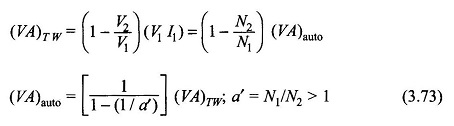
It immediately follows that
![]()
It is therefore seen that a two-winding transformer of a given VA rating when connected as an autotransformer can handle higher VA. This is because in the Auto Transformer connection (Fig. 3.35) part of the VA is transferred conductively. It is also noted from Eq. (3.74) as a′ = N1/N2 (the autotransformation ratio) approaches unity,
![]()
It is for this reason that Auto Transformer is commonly used when turn-ratio needed is 2 or less, like in interconnecting two high-voltage systems at different voltage levels. For low voltage, low VA rating autotransformer is used to obtain a variable voltage supply for testing purposes. Here a’ = N1/N2 is varied by changing the N2-tap.
It will also be shown in the example that follows that an autotransformer compared to its two-winding counterpart has a higher operating efficiency.
Let us see the problem from the design point of view by comparing winding copper needed for a given voltage ratio and VA rating for a two-winding transformer and an autotransformer. Assuming constant conductor current density, we can write

where G stands for weight of winding material. It then follows from Eq. (3.76) that

If a’ = 10, saving is only 10% but for a’ = 1.1, saving is as high as 90%. Hence the use of autotransformer is more economical when the turn-ratio is close to unity.
The interconnection of EHV systems (e.g. 220 kV and 132 kV) by the autotransformers results in considerable saving of bulk and cost as compared to the conventional two-winding transformers. Of course, a 3-phase autotransformer will be required.
It can be easily shown with reference to Fig. 3.35 that
