Diode Bridge Type Modulator with Transformer Coupling:
Diode Bridge Type Modulator – Figure 14.33 shows a silicon diode ring modulator with an associated ac coupled dc amplifier. The amplifier itself has a gain of 65 db and a flat response within ± 1 db, from 8 Hz to 80 kHz. Precautions are taken to safeguard the amplifier against sudden surge voltages having an active magnitude above the supply voltage of 9 V dc by using a 10 V zener diode as a guard element.
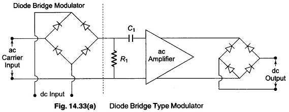
The function of diode bride modulator can be best understood from Fig. 14.33 (a). The device can be regarded as a polarity sensitive switch in which the ac excitation current cycles turn the input dc ON or OFF.
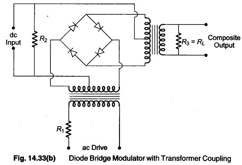
The signal is developed across the resistor R1 and coupled to the amplifier via the capacitor C1. Each pair of diodes conducts on alternate half cycles of the ac excitation. During one half cycle, the effect is to open the path between the dc signal input and the follow up ac amplifier. During the interval of the other cycle, the conductance path is closed. A transformer may be inserted for electrical isolation and/or voltage boosting as shown in Fig. 14.33 (b).
The modulator circuit shown in Fig. 14.33 (b) uses a conventional diode bridge which modulates low level dc signal (across R2), amplify the modulated signal, and then demodulates it to obtain the dc signal at high level. The centre taps of the transformer are critical for successful operation, and the silicon diodes used here require matched forward characteristics and a reverse current smaller than 10-8 A.
The output waveform is basically a square wave filtered by the output transformer. The amplitude of the output signal available across R3 is proportional to the magnitude of the dc input signal. The phase of the output signal with respect to the carrier signal is proportional to the sign of the dc signal.