Determination of the Synchronous Reactance | Open Circuit and Short Circuit test of Synchronous Machine:
Determination of the Synchronous Reactance – With the assumption of a linear magnetic circuit, the circuit model (per phase) of a synchronous machine is as given in Fig. 8.10c. If Ra is neglected, it then follows that
![]()
It is immediately seen from Eq. (8.22) that for a given field current under short-circuit condition (Ia = ISC, Vt = 0),
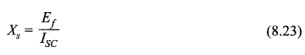
But Ef = VOC (open-circuit voltage, i.e. Ia = 0 with the same field current).
Then with the linearity assumption
where VOC = open circuit voltage and ISC = short-circuit current on a per phase basis with the same field current.
Since the magnetization characteristic of the machine is nonlinear, it is necessary to determine the complete open-circuit characteristic (OCC) of the machine (VOC – If relationship). However, it will soon be shown that it is sufficient to determine one point on the short-circuit characteristic (SCC) of the machine (ISC – If relationship) as it is linear in the range of interest (for ISC up to 150% of the rated current).
Open-Circuit Characteristic of Synchronous Machine (OCC):
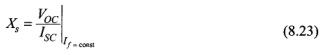
In this test the machine is run mechanically at synchronous speed ns to generate voltage at the rated frequency, while the armature terminals are open-circuited as in Fig. 8.11 with switch S open. The readings of the open-circuit line-to-line armature voltage, VOC = √3 Ef, are taken for various values of If, the rotor field current. It may be noted that If is representative of the net mmf/pole acting on the magnetic circuit of the machine. These data are plotted as OCC in Fig. 8.12 which indeed is the magnetization characteristic, i.e. the relation between the space fundamental component of the air-gap flux and the net mmf/pole acting on the magnetic circuit (space harmonics are assumed negligible).
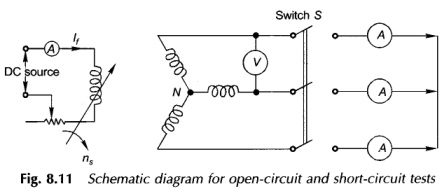
The OCC exhibits the saturation phenomenon of the iron in machine. At low values of If when iron is in the unsaturated state, the OCC is almost linear and the mmf applied is mainly consumed in establishing flux in the air-gap, the reluctance of the iron path being almost negligible. The straight-line part of the OCC, if extended as shown dotted in Fig. 8.12, is called the air-gap line and would indeed be the OCC if iron did not get saturated.
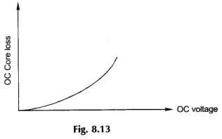
The open-circuit test conducted at rated voltage gives the constant loss of the synchronous machine comprising no-load (OC) core-loss and mechanical loss due to windage and friction. The power corresponding to these losses is drawn from the prime mover running the machine and can be measured by means of a dynamometer or torque meter. Their separation into the two components is easily carried out by running the machine at synchronous speed under an unexcited state. The core loss which comprises eddy current and hysteresis losses which vary as square and 1.6th power of open circuit voltage. The plot of core loss versus open circuit voltage is shown in Fig. 8.13.
Short-Circuit Characteristic (SCC):
The short-circuit characteristic of the machine is obtained by means of the short-circuit test conducted as per the schematic circuit diagram of Fig. 8.11 with switch S closed. While the rotor is run at synchronous speed ns, the rotor field is kept unexcited to begin with. The field excitation is then gradually increased till the armature current equals about 150% of its rated value. While the current in all the three ammeters should be identical, practically a small unbalance will always be found on account of winding and field current dissymmetries which cannot be completely avoided in a machine. Therefore ISC the short-circuit current per phase is taken as the average value of the three ammeter readings.
It is to be noted that the machine must not be short-circuited under excited conditions with a near about rated voltage. This can give rise to intolerably large transient currents in the machine.
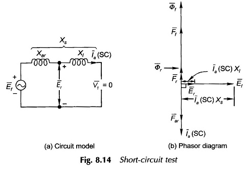
The circuit model of the machine under short-circuit conditions is given in Fig. 8.14(a) and the corresponding phasor diagram in Fig. 8.14(b) wherein Ra = 0. Since the armature circuit is assumed purely inductive, the short-circuit current lags the air-gap voltage Er by 90° so that the armature reaction mmf phasor Far is in direct opposition to Ff, i.e. the armature reaction is fully demagnetizing in effect.
The air-gap voltage needed to circulate the short-circuit current in the armature is given by
![]()
As Xl is about 0.1 to 0.2 pu (while Xs may be as high as 1.0 pu), Er is very small even when Ef has a value close to rated voltage of the machine. This implies that under the short-circuit condition with the armature current as high as 150% of the rated value, and resultant air-gap flux is small and so the machine is operating under the unsaturated magnetization condition so that the SCC (ISC versus If) is linear and therefore only one-short circuit reading is necessary for the complete determination of the SCC as shown in Fig. 8.12.
Since under the short-circuit condition the machine is highly under excited, the losses as drawn in from the mechanical shaft drive comprise mechanical loss and copper-loss in the resistance of the armature, the iron-loss being negligible.
The unsaturated synchronous reactance can be obtained from the OCC and SCC of Fig. 8.12 as
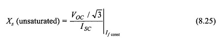
where If corresponds to the unsaturated magnetic region or VOC value corresponding to the air-gap line could be used.
Since a synchronous machine under operating conditions works in a somewhat saturated region of the magnetization characteristic, the performance of the machine as calculated from Xs, defined above, will differ considerably from the actual value effective during normal operation. To account for the fact that the machine actually operates in the saturated region, it is a must to resort to the nonlinear analysis or use a heuristic technique of adjusting Xs to a suitable value.
If Xs, as defined in Eq. (8.25), is plotted for various values of the field current, the chain-dotted curve of Fig. 8.12 will be obtained. Initially in the unsaturated region the value of the synchronous reactance remains constant at Xs (unsaturated) and then drops off sharply because of saturation of the OCC.
The value of Xs corresponding to the field current, which gives rated voltage on open-circuit, is defined as
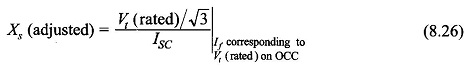
The value of Xs, (adjusted) is less than Xs (unsaturated) as shown in Fig. 8.12. Obviously Xs (adjusted) would yield the machine performance figures closer to those obtained under actual operation.
Short-circuit Ratio of Synchronous Reactance (SCR):
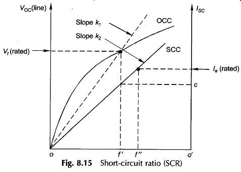
The short-circuit ratio (SCR) is defined as the ratio of the field current required to produce rated voltage on open-circuit to the field current required to produce rated armature current with the armature terminals shorted while the machine is mechanically run at synchronous speed. From the OCC and SCC as shown in Fig. 8.15,
as per the definition. It is further noted from this figure that
and slopes of OCC and SCC are
Substituting Eqs (8.29), and (8.30) in Eq. (8.27),
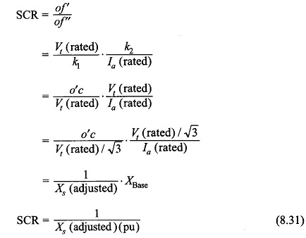
Equation (8.31) means that SCR is the reciprocal of Xs (adjusted) in pu. Therefore, a low value of SCR implies a large value of Xs (adjusted) (pu) and vice versa.
Short Circuit Loss of Synchronous Reactance:
During the short circuit test the loss can be obtained by measuring the mechanical power required to drive the machine. The loss comprises the following items:
- I2R loss in armature winding due to the flow of short circuit current (ac).
- Local core loss caused by armature leakage flux.
- Core loss due to resultant air-gap flux. As the flux is very small (see Fig. 8.14 (b)), this loss can be ignored.
- Windage and friction loss.
The windage and friction loss can be separated out by measuring mechanical power needed to drive the machine (at synchronous speed) with armature open circuited and field unexcited. The remaining loss (items 1 and 2) is called short circuit load loss whose plot with armature current is shown in Fig. 8.16. By measuring armature dc resistance correcting it for ac and to the armature temperature during SC test, dc I2R loss can then be subtracted leaving behind the stray load loss — sum of load core loss and loss due to additional conductor resistance offered to alternating current. The stray load Joss is also plotted in Fig. 8.16.
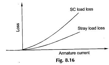
Armature current Fig. 8.16 The armature resistance as calculated from armature current and short circuit load loss is called effective armature resistance. It can be calculated at rated current and then assumed to remain constant. Thus
![]()