Resistance Thermometer Working Principle:
The resistance of a conductor changes when its temperature is changed. This property is utilized for the measurement of temperature. The Resistance Thermometer working principle is an instrument used to measure electrical resistance in terms of temperature, i.e. it uses the change in the electrical resistance of the conductor to determine the temperature.
The main part of a resistance thermometer working principle is its sensing element. The characteristics of the sensing element determines the sensitivity and operating temperature range of the instrument.
(There are three common types of temperature sensitive resistive elements in use, the wire wound resistance, the thermistor and the PTC semiconductor resistance.)
The sensing element may be any material that exhibits a relatively large resistance change with change in temperature. Also, the material used should be stable in its characteristics, i.e. neither its resistance nor its temperature coefficient of resistance should undergo permanent change with use or age.
To maintain the calibration of a resistance thermometer working principle, it is necessary to consider its stability. The need for stability frequently limits the temperature range over which the sensing element may be used.
Another desirable characteristic for a sensing element is a linear change in resistance with change in temperature.
The speed with which a resistive element responds to changes in temperature is important when the measured temperature is subjected to rapid variations. The smaller a given sensing element, the less heat required to raise its temperature, and the faster its response.
Platinum, nickel and copper are the metals most commonly used to measure temperature. The resistivity of platinum tends to increase less rapidly at higher temperatures than for other metals, hence it is a commonly used material for resistance thermometers. The temperature range over which platinum has stability is – 260 – 1100°C.
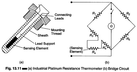
Figure 13.11(a) shows an industrial platinum resistance thermometer. The changes in resistance caused by changes in temperature are detected by a Wheatstone bridge, as shown in Fig. 13.11(b). Hence, the temperature sensing element, which may be nickel, copper or platinum contained in a bulb or well, along with the balancing bridge, form the essential components of a temperature measuring system based upon this principle.
The sensing element Rs is made of a material having a high temperature coefficient, and R1, R2, and R5 are made of resistances that are practically constant under normal temperature changes.
When no current flows through the galvanometer, the normal principle of Wheatstone’ s bridge states the ratio of resistance is

In normal practice, the sensing element is away from the indicator, and its leads have a resistance, say R3, R4.
Therefore,

Now it resistance Rs changes, balance cannot be maintained and the galvanometer shows a deflection, which can be calibrated to give a suitable temperature scale.
Advantages of Resistance Thermometer:
The measurement of temperature by the electrical resistance method has the following advantages and characteristics.
- The measurement is very accurate.
- It has a lot of flexibility with regard to choice of measuring equipment.
- Indicators, recorders or controllers can also be operated.
- More than one resistance element can be clubbed to the same indicating/ recording instrument.
- The temperature sensitive resistance element can be easily installed and replaced.
- The accuracy of the measuring circuit can be easily checked by substituting a standard resistor for the resistive element.
- Resistive elements can be used to measure differential temperature.
- Resistance thermometers have a wide working range without loss of accuracy, and can be used for temperature ranges (-200°C to + 650°C).
- They are best suited for remote indication.
- The resistive element response time is of the order of 2 to 10s
- The limits of error of a resistive element are ± 0.25% of the scale reading.
- The size of the resistive element may be about 6 – 12 mm in diameter and 12 – 75 mm in length.
- Extremely accurate temperature sensing.
- No necessity of temperature compensation.
- Stability of performance over long periods of time.
Limitations of Resistance Thermometer:
- High cost
- Need for bridge circuit and power source
- Possibility of self-heating
- Large bulb size, compared to a thermocouple