High Voltage Laboratory Rating:
The High Voltage Laboratory Rating and size of test equipment chosen in the h.v. laboratories depends on the test facilities to be provided. Normally, the design of the laboratories for 230 kV system voltage and below does not pose any problems, but laboratories intended for system voltages of 400 kV and above require special attention.
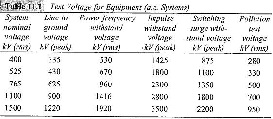
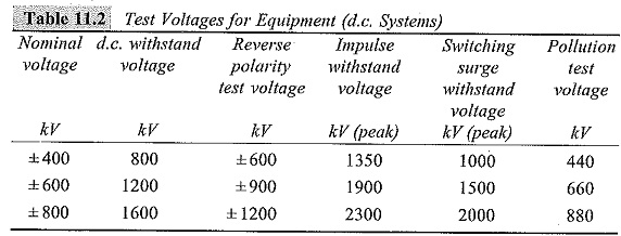
In Tables 11.1 and 11.2 various test voltages for different transmission system voltages are given.
For research and development work, the voltage levels needed are usually about 1.3 times the maximum test voltage needed. Hence, the labOratories intended for different system voltages should have the test voltages as available in Tables 11.3 and 11.4.
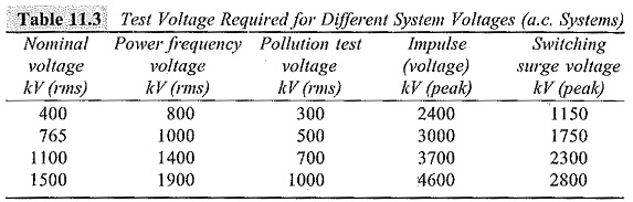
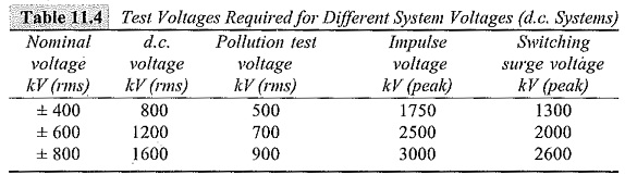
From the values given in Tables 11.3 and 11.4, one can conclude that laboratories intended for testing and development of equipment for 1000 kV a.c. systems require test transformers of 1.5 to 2.0 MV, impulse generator rated for 5 to 6 MV, and h.v.d.c. rectifiers of 1.2 to 1.5 MV.
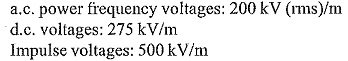
High voltage laboratories intended for system voltages of 400 kV or less need not go for such super high voltage rated equipment. The insulation levels for 400 kV system equipment are given below.
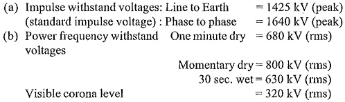
For the above data it may be concluded that a factor of more than 3 for impulse voltages and a factor of 2 to 2.5 for power frequency voltages (highest line to ground peak voltages) are adopted for system voltages of 400 kV and less. Hence, the High Voltage Laboratory Rating of the equipment should be at least about 900 kV (rms) for power frequency and 2000 kV (peak) for impulse voltages. The High Voltage Laboratory Rating of the equipment will be still less, if the laboratories are intended for system voltages of 132 kV or 230 kV and may be arrived at by considering the test voltages required.
Voltage and Power Ratings of Test Equipment
(a) d.c. Testing Equipment:
High voltage d.c. tests are performed using cascaded rectifiers. Careful consideration is necessary when tests on polluted insulation are to be performed which require currents of 50 to 200 mA, but strong predischarge streamers of 0.5 to 1.0 A of milliseconds duration may occur. Hence, the generator must have adequate internal reactance in order to maintain the test voltage without too high a voltage drop. The voltage ratings are given in Table 11.4, and the power rating may vary from a few kW to a few hundred kW.
(b) Power Frequency Testing Equipment:
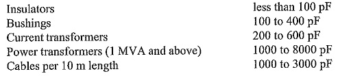
It is known that the flashover voltage of an insulator in air or oil or in some fluid depends on the capacitance of the supply system, due to the fact that a voltage drop may not maintain the predischarges before breakdown. Hence, a minimum, of about 1000 pF or more in parallel with the energized insulator is needed to determine the real flashover or puncture voltage, and the generator has to supply at least 1 A in the case of clean and 5 A in the case of polluted insulator at test voltage on short circuit. Approximate values of the self-capacitances of different equipments are given below:
The output of testing transformer will be given by
![]()
where,
f = supply frequency,
C = capacitance in pF, and
V = test voltage at the transformer terminals in kV (rms).
The transformer self-capacitance and the capacitances of various high voltage leads (bushings), etc. should also be included in determining the load capacitance. From the above figures it is implied that the minimum power rating of a 1 MV testing transformer will be about 300 kVA. Usually, the power rating of a testing transformer in kVA (single unit) is approximately taken to be equal to the High Voltage Laboratory Rating in kV.
(c)Impulse Generators:
The maximum charging voltage of an impulse voltage generator is given by the stage voltage multiplied by the number of stages. The peak value of the impulse voltage Vs for a standard 1.2/50 μs wave is
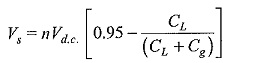
where,
Vd.c. = Charging voltage,
n = number of stage in the generator,
CL = load capacitance, and
C = generator capacitance
For Cg/CL ≥ 5, the peak value of the impulse generator output voltage will be approximately Vs ≈ 0.7 nVd.c.. In other words, the generator rating has to be at least 1.4 times more than the desired output voltage. The energy rating of the impulse generator at its maximum voltage rating is given by
![]()
where,
W = stored energy,
Cg = capacitance of the generator in pF, and
V = total charging voltage in kV.
In order to test transformers which have large capacitance, a minimum of 30,000 to 40,000 pF of generator capacitance is needed. A simple calculation will show that a minimum of 135 kJ is required for a 3 MV impulse generator, if the IEC specification for impulse waveshape is to be maintained. The minimum energy rating of a 6 MV impulse generator will be about 600 kJ. From this it may be concluded that the energy rating in kilojoules may be approximated to be equal to 0.1 times the High Voltage Laboratory Rating in kV.
There is no problem to pile up a large size capacitance in the form of a number of capacitors and to charge them in parallel and discharge them in series to give the required peak of the standard impulse wave. But many difficulties exist in reducing the internal inductance of the circuit to a minimum to obtain a steep front and to avoid oscillations. As an example, a 4 MV impulse generator test circuit has a length equal to the height of the generator plus twice the distance between the test object and the generator. The overall inductance of such a circuit including the internal inductance of the generator will easily be more than 140 μH. With such a generator, it is impossible to test an object of capacitance of 5000 pF with a front time of 1.2 μs and with less than 5% overshoot. Hence, a very careful design and a very careful consideration of the test circuit only can give the optimum test conditions which are not far from theoretical specifications.
The necessity of rapid change of the test circuit from standard impulse to switching surges requires careful studies for placing of series and parallel resistors when producing switching surges like 100/1000 μs or 200/2000 μs waveform, in which the efficiency of the generator is very much reduced. Also, the front time and the tail time resistors have to be carefully rated, as they have to dissipate larger amounts of energy than in the case of standard impulses.
(d) Other High Voltage Testing Equipment:
Usually, the other testing equipment will be available is,
(i) impulse current generators for testing lightning arresters,
(ii) test facilities for measuring RIV and partial discharges,
(iii) sphere gaps for measurement and calibration purposes, and
(iv) High voltage Schering bridge for dielectric testing.
Usually, the impulse current generators are rated between 100 and 250 kA with an energy rating of 50 to 100 kJ. This is more than adequate for testing with lightning stroke currents. Partial discharge and RIV measurements require testing transformers free from internal discharges. The detection equipment should be capable of detecting 0.01 pico coulomb of charge in a test object capacitance of 100 pF and 2 to 3 pico coulombs at 1 μF test capacitance. Therefore, the test transformers should have internal discharges of the same order or less at the specified voltage value. Nowadays, it is possible to design a.c. testing transformers with necessary shielding, etc. with internal discharges less than 5 pC at 5000 kV.
Size and Dimensions of the Equipment in High Voltage Laboratories:
High voltage laboratories may be either (a) indoor type or (b) outdoor type. The indoor type has the advantage of protection of testing equipment against variable weather conditions, simplicity in design and control of the test equipment, and provision of observation facilities during testing. But outdoor laboratories have the advantage of less cost due to the absence of building cost and the planned facility layout cost. But outdoor test areas have limitations such as
- absence of lifting and supporting facilities,
- climatic conditions which may restrict or impede testing,
- reproducibility of results not being guaranteed due to uncontrolled atmospheric conditions, and
- artificial and wet test studies which are difficult due to wind variation, etc.
When high voltage laboratories are planned as indoor laboratories, the following figures fix the dimensions of the laboratories:
- Size of the test‘equipment for a.c., d.c., or impulse generators.
- Distances or clearances between the test object and ground during test conditions and also between all the high voltage terminals and earthed or grounded surroundings such as walls, roofs of buildings, and other test equipment not energized.
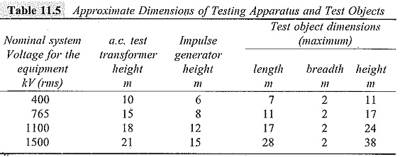
In Table 11.5 are given the approximate size and dimensions of the test transformers and impulse generators for different system voltages. The table also gives minimum room to be provided for the equipment.
Regarding clearances, that is, the minimum distance between the high voltage surfaces and the ground points; they are of utmost importance in high voltage testing.
The approximate working clearances recommended are as follows:
For switching surges, the clearance is worked out from the following approximate formula
![]()
where d is in m, and V in MV.
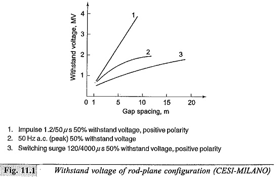
The above clearances are safe, as long as the test voltages do not exceed 1.5 MV for a.c. and d.c. voltages and 2.5 MV for impulse and switching surge voltages. For higher voltages, clearances have to be worked out by considering the withstand voltages for rod-plane configuration. The characteristic is given in Fig. 11.1. The necessary distances to the surroundings for switching surges of a long duration will be about 12 m for 760 kV and 30 m for 1500 kV system voltage equipment. Hence, from the above data and from Fig. 11.1 it is evident that the h.v. laboratories rated for 400 kV and above are practically conditioned by the necessary clearances for switching surge tests.
Layout of High Voltage Laboratories:
The layout of an h.v. laboratory is an important aspect for providing an efficient testing facility. Laboratory arrangements differ very much from a single equipment to multi d.c., a.c., and impulse arrangements in different testing programmes. Each laboratory has to be designed individually considering the type of equipment to be tested, the available space, other accessories needed for the tests, the storage space required, etc. Earthing, control gear, and the safety precautions require most careful consideration.
Laboratory Building:
The building construction is not critical except where ionization tests are conducted. To minimize the floor loading problems and to simplify earthing arrangement, a ground level location is preferred. The floor should withstand the loading imposed by the equipment and test objects. Arrangements should be made to ensure that the laboratory is free from dust, draught, and excessive humidity. Laboratory windows may require blackout arrangement for visual corona tests, etc. The control room should be located in such a way as to include good overall view of the laboratory and test area. The main access door to the test area must accommodate the test equipment and the test object and have adequate interlocking arrangements and warning systems to ensure safety to the personnel. A typical layout of a high voltage laboratory accommodating a 1.0 MV a.c. testing transformer and a 3 MV impulse generator is shown in Fig. 11.2. The dotted circles indicate the clearances necessary.