Transformer Coupled Amplifier

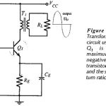
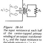
Transformer Coupled Amplifier: Transformer Coupled Amplifier commences with the load resistance and output power, specification. A signal voltage amplitude may also be stated, as well as the upper and lower…

Continue Reading Transformer Coupled Amplifier
Transformer Coupled Class B Amplifier

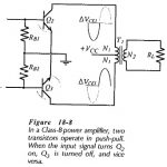
Transformer Coupled Class B Amplifier: Class B Amplifier - The inefficiency of Class-A amplifiers is largely due to the transistor bias conditions. In a Class-B amplifier, the transistors are biased…

Continue Reading Transformer Coupled Class B Amplifier

Transformer Coupled Class A Amplifier

Transformer Coupled Class A Amplifier: Class A Circuit - Instead of capacitor coupling, a Transformer Coupled Class A Amplifier may be used to ac couple amplifier stages while providing dc…

Continue Reading Transformer Coupled Class A Amplifier

Operational Amplifier Circuit Stability

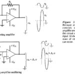
Operational Amplifier Circuit Stability: Loop Gain and Loop Phase Shift - Consider the inverting amplifier circuit and waveforms in Fig. 15-­1(a). The signal voltage voltage (vs) is amplified by a…

Continue Reading Operational Amplifier Circuit Stability

Instrumentation Amplifier Circuit Working

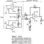
Instrumentation Amplifier Circuit Working: Circuit Operation - At first glance, the Instrumentation Amplifier Circuit Working in Fig. 14-28 looks complex, but when considered section by section it is found to…

Continue Reading Instrumentation Amplifier Circuit Working

Direct Coupled Inverting Amplifier

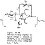
Direct Coupled Inverting Amplifier: The circuit in Fig. 14-18 is termed an Direct Coupled Inverting Amplifier because, with Vi applied via R1 to the inverting input terminal, the output goes negative when…

Continue Reading Direct Coupled Inverting Amplifier

Non Inverting Amplifier Theory

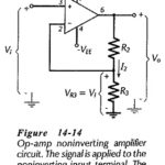
Non Inverting Amplifier Theory: Direct-Coupled Noninverting Amplifier - The Non Inverting Amplifier Theory circuit in Fig. 14-14 behaves similarly to a voltage follower circuit with one major difference. Instead of…

Continue Reading Non Inverting Amplifier Theory

Integrated Circuit Operational Amplifier

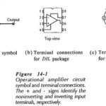
Integrated Circuit Operational Amplifier: Circuit Symbol and Packages - Figure 14-1(a) shows the triangular circuit symbol for an Integrated Circuit Operational Amplifier (op-amp). As illustrated, there are two input terminals,…

Continue Reading Integrated Circuit Operational Amplifier