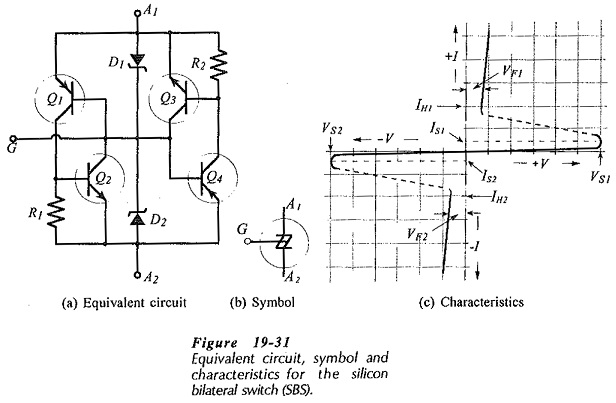
Silicon Bilateral Switch
Silicon Bilateral Switch: It might be convenient to think of a Silicon Bilateral Switch (SBS) as an SUS with a gate terminal, or as a low-current TRIAC. However, the SBS is not simply another four-layer device.…
Comments Off on Silicon Bilateral Switch
April 6, 2019