Diode Applications

Diode Logic Circuits

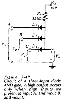
Diode Logic Circuits: A Diode Logic Circuits produces an output voltage which is either high or low, depending upon the levels of several input voltages. The two basic logic circuits are the AND gate and the OR gate. Diode AND Gate: Figure 3-49 shows the circuit diagram of a diode AND gate. It is seen […]

Diode Logic Circuits Read More »

Voltage Doubler Circuit

Voltage Doubler Circuit: A Voltage Doubler Circuit produces an output voltage which is approximately double the peak voltage of the input waveform. Consideration of the voltage doubler circuit diagram in Fig. 3-42 shows that it is simply a combination of two diode-capacitor clamping circuits without the discharge resistors. In fact, the circuit operation is similar

Voltage Doubler Circuit Read More »

Clamping Circuit

Clamping Circuit: Negative and Positive Voltage Clamping Circuits – A clamping circuit, also known as a dc restorer, changes the dc voltage level of a waveform, but does not affect its shape Consider the clamping circuit shown in Fig. 3-33. When the square wave input is positive, diode D1 is forward biased, and voltage equals

Clamping Circuit Read More »

Shunt Clipping Circuits

Shunt Clipping Circuits: A positive Shunt Clipping Circuits is illustrated in Fig. 3-28(a). Here the diode is connected in shunt (or parallel) with the output terminals. When the input is negative, the diode is reverse biased and only a small voltage drop occurs across RI, due to load current IL. This means that the circuit

Shunt Clipping Circuits Read More »

Diode Series Clipper Circuit

Diode Series Clipper Circuit: The function of a Diode Series Clipper Circuit (or limiter) is to clip off an unwanted portion of a waveform. This is sometimes necessary to protect a device or circuit that might be destroyed by a large amplitude (negative or positive) signal. A half-wave rectifier can be described as a clipper,

Diode Series Clipper Circuit Read More »

Full Wave Rectifier DC Power Supply

Full Wave Rectifier DC Power Supply: Like half-wave rectifiers, full-wave rectifiers require filter circuits to convert the output waveform to direct voltage. Figure 3-13 shows a Full Wave Rectifier DC Power Supply with a reservior capacitor and a surge limiting resistor. These components operate exactly as explained for the half-wave rectifier circuit, with a few

Full Wave Rectifier DC Power Supply Read More »

Two Diode Full Wave Rectifier Circuit

Two Diode Full Wave Rectifier Circuit: The Fig. 3-2 shows the Two Diode Full Wave Rectifier Circuit, and its input voltage is supplied from a transformer (T1) with a center-tapped secondary winding. The circuit is essentially a combination of two half-wave rectifier circuits, each supplied from half of the transformer secondary. When the transformer output

Two Diode Full Wave Rectifier Circuit Read More »

Scroll to Top