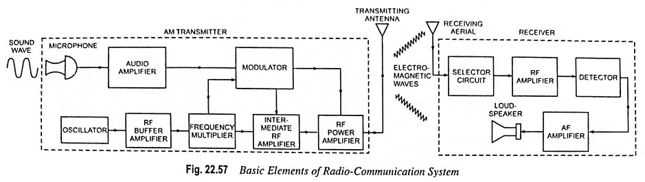
Radio Communication System – Block Diagram and types
Radio Communication System - Block Diagram and types: Radio communication is very popular technique of communicating a message. The radio waves are electromagnetic waves produced due to escape of electrical energy into free space. They…
Comments Off on Radio Communication System – Block Diagram and types
December 2, 2022