Complementary Symmetry Push Pull Amplifier
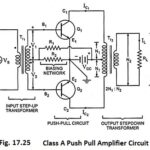
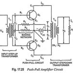
Complementary Symmetry Push Pull Amplifier: The use of transformers, at input as well as at output ends, in the push-pull amplifier shown in Fig. 17.25 makes it bulky and expensive…
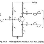
Phase Splitter Circuit for Push Pull Power Amplifiers (or Phase Inverter): In a push-pull amplifier circuit an input transformer is used to provide the polarity inversion between the two input…
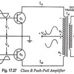
Class B Push Pull Amplifier - Circuit Diagram, Operation and Derivation: The circuitry for the Class B Push Pull Amplifier operation is the same as that for the class A…
Class A Push Pull Amplifier - Working Principle, Advantages & Disadvantages: A Class A Push Pull Amplifier circuit is shown in Fig. 17.25. By Class A Push Pull Amplifier means…
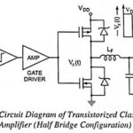
Class D Power Amplifiers - Circuit Diagram, Operation and Applications: Historically, audio amplifiers have been configured as class A, class B or class AB and the art of design is…
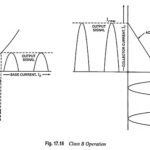
Class B Power Amplifier - Operation and Efficiency derivation: In Class B Power Amplifier operation, the transistor is so biased that zero signal collector current is zero. Hence class B…
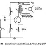
Transformer Coupled Class A Power Amplifier: Transformer Coupled Class A Power Amplifier also sometimes referred to as single ended power amplifier. The term "single ended" (denoting only one transistor) is…
Class A Power Amplifiers (Direct Coupled with Resistive Load): A class A power amplifiers is defined as a power amplifier in which output current flows for the entire cycle (360°)…