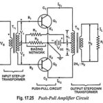
Push Pull Amplifier – Circuit Diagram and its Workings
Push Pull Amplifier - Circuit Diagram and its Workings: As we know already that, double-ended or push pull amplifiers makes use of two identical transistors in a single stage. It consists of…
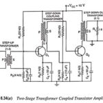
Transformer Coupled Transistor Amplifier - Working Principle: The main cause for low voltage and power gains of an R-C coupled amplifier is that the effective load (Rac) of each stage…
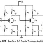
RC Coupled Transistor Amplifier - Operations, Derivation and Applications: A two-stage RC Coupled Transistor Amplifier using N-P-N transistors in CE configuration is shown in Fig. 16.12. The two transistors used are…
Noise in Amplifiers and its Types: Noise in Amplifiers - Noise is any kind of unwanted signal that is not related to the input. Any electronic component produces a certain…
Difference between JFET and MOSFET: The Difference between JFET and MOSFET are quite similar in their operating principles and in their electrical characteristics. However, they differ in some aspects, as…
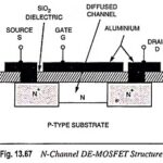
Depletion Type MOSFET - Construction, Operation and Characteristics: As we know already that when the gate is biased negative w.r.t. the source in an N-channel JFET, the depletion-region widths are…
Selection of Oscillator: While in the Selection of Oscillator for a particular application, the following particulars are to be considered. Frequency Range: The oscillator selected for a particular application should…
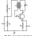
Tuned Collector Oscillator - Definition, Working and Equation: The basic circuit of a tuned collector oscillator is shown in Fig. 21.7. It is called the tuned collector oscillator, because the…