DC Load Line of BJT Biasing Circuit
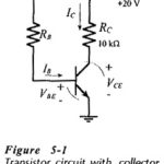
DC Load Line of BJT Biasing Circuit: The DC Load Line of BJT Biasing Circuit is a straight line drawn on the transistor output characteristics. For a common-emitter (CE) circuit,…
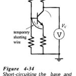
Transistor Testing Circuit: In-Circuit Testing - A quick test to check if a transistor is operational can be performed while the device is still connected in a circuit. Consider Fig.…
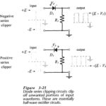
Diode Series Clipper Circuit: The function of a Diode Series Clipper Circuit (or limiter) is to clip off an unwanted portion of a waveform. This is sometimes necessary to protect…
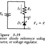
Zener Diode Voltage Regulator Circuit: Regulator Circuit With No Load - The most important application of Zener Diode Voltage Regulator Circuit is dc voltage regulator circuits. These can be the…
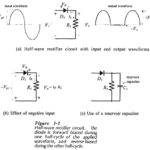
Half Wave Rectifier Circuit: A basic diode Half Wave Rectifier Circuit is shown in Fig. 3-1(a). An alternating input voltage is applied to a single diode connected in series with…
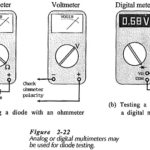
Testing of Semiconductor Diode: There are Several methods are available for Testing of Semiconductor Diode, namely, Ohmmeter Tests: One of the simplest and quickest tests can be made using an ohmmeter…
Temperature Effect on Semiconductor Diode: Diode Power Dissipation - The power dissipation in a diode is simply calculated as the device terminal voltage multiplied by the current level. Device manufacturers…
Diode Approximations: Diode Approximations - As we know already that, a diode is essentially a one-way device, offering a low resistance when forward biased, and a high resistance when biased…