Mathematical Formulation of Voltage Stability:
Mathematical Formulation of Voltage Stability – The slower forms of voltage instability are normally analyzed as steady state problems using power flow simulation as the primary study method. “Snapshots” in time following an outage or during load build up are simulated. Besides these post-disturbance power flows, two other power flow based methods are often used; PV curves and VQ curves. These two methods give steady-state loadability limits which are related to voltage stability. Conventional load flow programs can be used for approximate analysis.
P–V. curves are useful for conceptual analysis of voltage stability and for study of radial systems.
The model that will be employed here to judge voltage stability is based on a single line performance. The voltage performance of this simple system is qualitatively similar to that of a practical system with many voltage sources, loads and the network of transmission lines.
Consider the radial two bus system of Fig. 17.1. Here E is Vs and V is VR and E and V are magnitudes with E leading V by δ. Line angle Φ = tan-1 X/R and |z| ≈ X.
In terms of P and Q, the system load end voltage can be expressed as
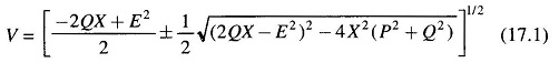
It is seen from Eq. (17.1) that V is a double-valued function (i.e. it has two solutions) of P for a particular pf which determines Q in terms of P. The PV curves for various values of pf are plotted in Fig. 17.2. For each value of pf, the higher voltage solution indicates stable voltage case, while the lower voltage lies in the unstable voltage operation zone. The changeover occurs at Vcri(critical) and Pmax. The locus of Vcri – Pmax points for various pfs is drawn in dotted line in the figure. Any attempt to increase the load above Pmax causes a reversal of voltage and load. Reducing voltage causes an increasing current to be drawn by the load. In turn the larger reactive line drop causes the voltage to dip further. This being unstable operation causes the system to suffer voltage collapse. This is also brought out by the fact that in upper part of the curve dP/dV<0 and in the lower part (unstable part) dP/dV>0 (reducing load means reducing voltage and vice-versa). It may be noted here that the type of load assumed in Fig. 17.2 is constant impedance. In practical systems the type of loads are mixed or predominantly constant power type such that system voltage degradation -is more and voltage instability occurs much prior to the theoretical power limit.
As in the case of single line system, in a general power system, voltage instability occurs above certain bus loading and certain Q injections. This condition is indicated by the singularity of the Jacobian of Load Flow equations and level of voltage instability is assessed by the minimum singular value.
Certain results that are of significance for voltage stability are as under.
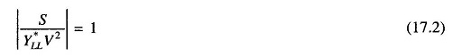
- Voltage stability limit is reached when
where
- S = complex power at load bus
- YLL = load bus admittance
- V = load bus voltage
Nearer the magnitude in Eq. (17.2) to unity, lesser the stability margin.
- The loading limit of a transmission line can be determined from
![]()
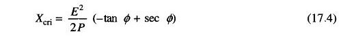
Xcri is the critical system reactance beyond which voltage stability is lost. It can be expressed as
We have so far considered how the PV characteristics with constant load power factor affect the voltage stability of a system. A more meaningful characteristic for certain aspects of voltage stability is the QV characteristic, which brings out the sensitivity and variation of bus voltage with respect to reactive power injections (+ve or -ve).
Consider once again the simple radial system of Fig. 17.1. For Q flow it is sufficiently accurate to assume X ≫ R i.e. Φ ≈ 90°. It then follows that
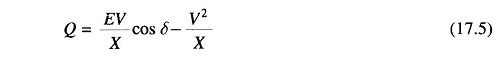
or
![]()
Taking derivative wrt V gives
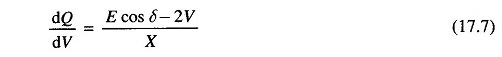
The QV characteristic on normalized basis (Q/Pmax, V/E) for various values of P/Pmax are plotted in Fig. 17.3. The system is voltage stable in the region where dQ/dV is positive, while the voltage stability limit is reached at dQ/dV = 0 which may also be termed as the critical operating point.
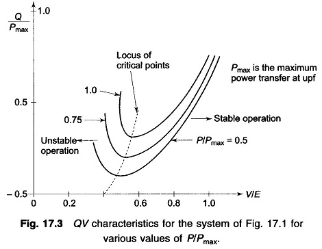
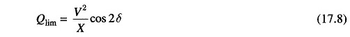
The limiting value of the reactive power transfer at the limiting stage of voltage Stability is given by
The inferences drawn from the simple radial system qualitatively apply to a practical size system. Other factors that contribute to system voltage collapse are: strength of transmission system, power transfer levels, load characteristics, generator reactive power limits and characteristics of reactive power compensating devices.