
Skip to content
  • Electrical and Electronics Interview Questions and Answers
    • Electronics Engineering Interview Questions and Answers
    • Electrical Power Engineering Interview Questions and Answers
    • Communication Engineering Interview Questions and Answers
    • Digital Signal Processing Interview Questions and Answers
    • High Voltage Engineering Interview Questions and Answers
    • Microprocessor and Microcontroller Interview Questions and Answers
    • Protection and Switchgear Interview Questions and Answers
    • Power Electronics Interview Questions and Answers
    • Transmission and Distribution Interview Questions and Answers
    • Power System Operation and Control Interview Questions and Answers
    • READ MORE –>
  • Viva Questions and Answers
    • Electrical Engineering viva Questions and Answers
    • Electronics Communication Engineering viva Questions and Answers
  • Multiple Choice Questions with Answers
    • Electronics Engineering Multiple Choice Questions with Answers
    • Electrical Power Engineering Multiple Choice Questions with Answers
  • Comparisons in Electrical and Electronics
    • Difference between 80186 and 80286 Microprocessor
    • Difference Between Star and Delta Connections
    • Difference Between Electric Circuit and Magnetic Circuit
    • Difference between Static RAM and Dynamic RAM
    • Difference between Linear Power Supply and SMPS
    • Difference Between Thyristor and Transistor
    • Difference Between PAM, PWM and PPM
    • Difference between Isolator and Circuit Breaker
    • Difference between JFET and MOSFET
    • Difference between NMOS and PMOS
    • READ MORE –>
EEEGUIDE.COM
  • HOME
  • Electronics Engineering
  • Electronic Communication
  • Electronic Instrumentation
  • Electronic Devices and Circuits
  • Microprocessors and Microcontrollers
  • Electrical Power Engineering
  • Electrical Machines
  • High Voltage Engineering
  • Fundamentals of Electrical Drives
  • Circuits and Networks
  • Integrated Circuits
  • Network Analysis and Synthesis
  • Modern Power System
  • Principles of Power System
  • Power System Protection and Switchgear
  • Power Plant Engineering
Menu Close
Toggle the button to expand or collapse the Menu
  • Electronics Engineering
  • Electronic Communication
  • Electronic Instrumentation
  • Electronic Devices
  • Microprocessors and Microcontrollers
  • Electrical Power Engineering
  • Electrical Machines
  • Electrical Drives
  • High Voltage Engineering
  • Circuits and Networks
  • Integrated Circuits
  • Network Analysis and Synthesis
  • Modern Power System
  • Principles of Power System
  • Power System Protection and Switchgear
  • Power Plant Engineering
  • Interview Questions and Answers
  • Multiple Choice Questions with Answers
  • Comparisons in Electrical and Electronics
  • Viva Questions and Answers

Block Diagram of a Shunt Voltage Regulator 04

Continue Reading Block Diagram of a Shunt Voltage Regulator 04

Block Diagram of a Shunt Voltage Regulator 03

Continue Reading Block Diagram of a Shunt Voltage Regulator 03

Block Diagram of a Shunt Voltage Regulator 02

Continue Reading Block Diagram of a Shunt Voltage Regulator 02

Block Diagram of a Shunt Voltage Regulator 01

Continue Reading Block Diagram of a Shunt Voltage Regulator 01
Transistor Series Voltage Regulator or Emitter Follower Voltage Regulator

Transistor Series Voltage Regulator or Emitter Follower Voltage Regulator

Transistor Series Voltage Regulator or Emitter Follower Voltage Regulator: A simple series voltage regulator using an NPN transistor and a zener diode is shown in Fig. 43.5. This circuit is…
Continue Reading Transistor Series Voltage Regulator or Emitter Follower Voltage Regulator

Transistor Series Voltage Regulator or Emitter Follower Voltage Regulator 02

Continue Reading Transistor Series Voltage Regulator or Emitter Follower Voltage Regulator 02

Transistor Series Voltage Regulator or Emitter Follower Voltage Regulator 01

Continue Reading Transistor Series Voltage Regulator or Emitter Follower Voltage Regulator 01
Series Voltage Regulator – Block Diagram and Working Principle

Series Voltage Regulator – Block Diagram and Working Principle

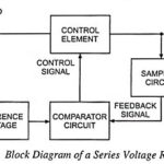
Series Voltage Regulator - Block Diagram and Working Principle: The basic connection of a series voltage regulator circuit is shown in the block diagram given in Fig. 43.4. The series…

Continue Reading Series Voltage Regulator – Block Diagram and Working Principle
  • Go to the previous page
  • 1
  • …
  • 3
  • 4
  • 5
  • 6
  • 7
  • 8
  • 9
  • …
  • 30
  • Go to the next page

Popular Articles

  • Triangular Wave Generator Using Op amp
  • Single Phase Full Wave Controlled Rectifier
  • Square Wave Generator Using Op amp
  • BCD Adder Circuit
  • Class B Push Pull Amplifier
  • Second Order Low Pass Butterworth Filter
  • Voltage Series Feedback Amplifier
  • Intel 8051 Architecture and 8031 Architecture
  • Single Phase Fully Controlled Rectifier Control of DC Motor
  • Darlington Amplifier
  • Op Amp IC 741 Pin Diagram and its Working
  • IC 723 Voltage Regulator
  • Transient Response of RL Circuit
  • Load Frequency Control of Single Area System
  • Voltage Divider Bias Circuit
  • Voltage Shunt Feedback Amplifier Circuit
  • First Order Low Pass Butterworth Filter
  • Second Order High Pass Butterworth Filters
  • Internal Architecture of 8086
  • Precision Full Wave Rectifier

Recent Articles

  • Elemental Semiconductor Materials
  • What is Analog Signal and Digital Signal?
  • What is Multistage Amplifier? – Types, Block Diagram and Analysis
  • Current Controlled Current Source (CCCS) Circuit
  • Light Activated SCR (LASCR) – Symbol, Construction and Operation
  • Relaxation Time, Collision Time and Mean Free Path
  • Construction and Working of Zener Diode
  • AC Regulator – Definition and Classification
  • Transistor Clipper Circuit and Waveforms
  • What is Optoelectronic Devices?
  • Single Phase Dual Converter Circuit Diagram with Four Quadrant of Operation
  • Blocking Oscillator – Definition, Operation and Types
  • OTA Adder (Summer) and OTA Lossy Integrator
  • Transistor Circuit Configurations (CB, CE, CC)
  • Motion of an Electron in a Magnetic Field
  • Series Diode Configurations with DC Inputs
  • Current Series Feedback Amplifier Circuit
  • Common Drain JFET Amplifier or Source Follower
  • What is Diode Transistor Logic (DTL) Circuit?
  • Square Law Detector Circuit and Working Principle

Active users on site

  • HOME
  • PRIVACY POLICY
  • CONTACT US
  • SITEMAP
COPYRIGHT © 2014 TO 2026 EEEGUIDE.COM ALL RIGHTS RESERVED