AC Analysis of BJT Circuits Articles
AC Analysis of BJT Circuits Articles: Coupling and Bypassing Capacitors: Coupling Capacitors – To use a transistor circuit to amplify or otherwise process an ac signal, the signal source must…
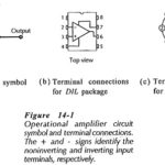
Integrated Circuit Operational Amplifier: Circuit Symbol and Packages - Figure 14-1(a) shows the triangular circuit symbol for an Integrated Circuit Operational Amplifier (op-amp). As illustrated, there are two input terminals,…
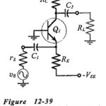
Capacitor Coupled Common Base Amplifier: A practical Capacitor Coupled Common Base Amplifier (using a plus/minus supply) is shown in Fig. 12-39. [Note the polarity of the input coupling capacitor (C1).]…
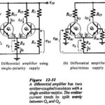
Differential Amplifier Circuit using Transistors: The Differential Amplifier Circuit using Transistors is widely applied in integrated circuitry, because it has both good bias stability and good voltage gain without the…
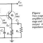
Two Stage Direct Coupled Common Emitter Amplifier: Figure 12-23 shows Two Stage Direct Coupled Common Emitter Amplifier. This time the second stage is a common collector circuit, or emitter follower.…
Single Stage Common Emitter Amplifier Circuit: Specification - Bias circuit design for the Single Stage Common Emitter Amplifier Circuit in shown in Fig. 12-1 and ac analysis of the circuit…
Difference Between Common Base Common Emitter and Common Collector: Table 6-2 compares Zi, Zo, and Av, for difference Between Common Base Common Emitter and Common Collector circuits. As already discussed, the…
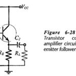
Common Collector Circuit Analysis: In the Common Collector Circuit Analysis (CC) shown in Fig. 6-28 the external load (RL) is capacitor-coupled to the transistor emitter terminal. The circuit uses voltage divider…