RC Integrator Circuit Diagram and its Application:
A circuit that gives an output voltage directly proportional to the integral of its input is known as integrating circuit.
![]()
Figure 29.18 shows a typical RC Integrator Circuit diagram. The output voltage across capacitor C will be the integral of the input voltage. It is important to note that merely an R-C series circuit will not provide voltage across capacitor C as an integral of the input.
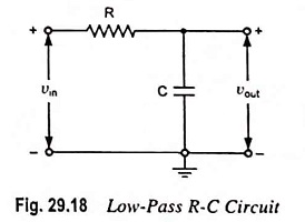
The conditions to be fulfilled for making an R-C series circuit as an integrator are given below.
- The time constant RC of the circuit should be very large as compared to the time period of the input signal i.e., RC >> T.
- The value of R should not be smaller than 10 times the capacitive reactance i.e., R ≥ 10 Xc or ≥ 10/2πfC.
When the given R-C circuit fulfills the above conditions, then the voltage appearing across capacitor C will be integral of the input. This is shown below.
Let vin be the input alternating voltage and i be the resulting alternating current. Since R is very large in comparison of capacitive reactance XC, the voltage drop across resistance R may be considered equal to input voltage i.e.,

The charge on the capacitor at any instant
![]()
and output voltage,
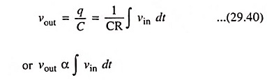
Hence output voltage
![]()
The output waveform from an RC Integrator Circuit depends upon the time constant of the circuit and shape of the input wave. When the input wave is a square wave, output will be a triangular wave. This is because integral of a constant is a linear ramp. For a rectangular input wave, the output will be a sawtooth wave.
Applications:
Integrators find application in generation of triangular and ramp waveforms, indiscriminating between pulses of different lengths as in separation of horizontal and vertical synchronizing pulses in television, in analog computers as integrator blocks.