Semiconductor Diodes in Static Relays
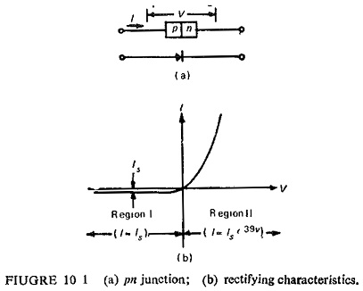
Semiconductor Diodes in Static Relays: Semiconductor Diodes in Static Relays - The pn junction has rectifying characteristics as shown in Fig. (10.1). If a source of emf is connected to the pn junction in the…
Semiconductor Diode Specifications: Diode Data Sheets - To select a suitable diode for a particular application, the data sheets, or Semiconductor Diode Specifications, provided by device manufacturers must be consulted. Portions of typical diode data…
Semiconductor Converter Controlled Drives: These are now widely used both in ac and dc tractions involving dc and ac motors, and the conventional drives have all become outdated, and will be phased out in near…
Self Oscillating Converter (Transistorized Chopper Circuit): Self Oscillating Converter (Transistorized Chopper Circuit) - A Transistorized dc to ac converter suitable for low level dc signal is illustrated in Fig. 14.30. The unique property of this…
Self GMD and Mutual GMD: Self GMD and Mutual GMD - The use of self geometrical mean distance (abbreviated as Self GMD) and mutual geometrical mean distance (Mutual GMD) simplifies the inductance calculations, particularly relating…
Self Excited DC Generator: Rather than arranging a separate dc source for excitation purposes, practical generators are always excited from their own armature terminals, this method of excitation being known as Self Excitation. A Self…
Self Controlled Synchronous Motor Drive Employing a Cycloconverter: Self Controlled Synchronous Motor Drive Employing a Cycloconverter as shown in Fig. 7.13. Firing pulses are generated either by comparison of the motor terminal voltages or by…
Self Controlled Synchronous Motor Drive: A Self Controlled Synchronous Motor Drive employing a load commutated thyristor inverter is shown in Fig. 7.10. In large power drives wound field synchronous motor is used. Medium power drives…
Self Bias or Potential Divider Bias Circuit: This is the most commonly used biasing arrangement. The arrangement of Self Bias or Potential Divider Bias Circuit is shown in Fig. 12.17 (a). The name voltage divider…
Self Bias Circuit Diagram: Circuit Operation - In a self bias JFET circuit, gate-source bias is provided by the voltage drop across a resistor in series with the device source terminal. Consider the n-channel JFET…