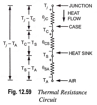
Thermal Resistance – Definition, Circuit Diagram and Equation
Thermal Resistance - Definition, Circuit Diagram and Equation: With power transistors, a designer often uses a heat sink to get a high power rating for the transistor. As already mentioned, the heat sink allows the…
Comments Off on Thermal Resistance – Definition, Circuit Diagram and Equation
November 13, 2022