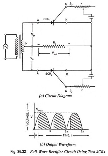
SCR as Full Wave Rectifier Circuit Diagram
SCR as Full Wave Rectifier Circuit Diagram: For Two SCR as Full Wave Rectifier are connected across the centre taped secondary, as shown in Fig. 26.32 (a). The gates of both SCRs are supplied from…
Comments Off on SCR as Full Wave Rectifier Circuit Diagram
December 3, 2022