IC Operational Amplifiers

Schmitt Trigger Circuit Diagram

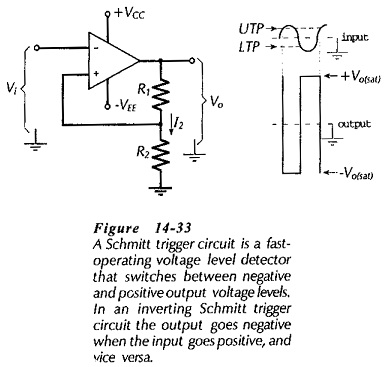
Schmitt Trigger Circuit Diagram: Inverting Schmitt Trigger – A Schmitt Trigger Circuit Diagram is a fast-operating voltage level detector. When the input voltage arrives at a level determined by the circuit components, the output voltage switches rapidly between its maximum positive level and its maximum negative level. An op-amp inverting Schmitt Trigger Circuit Diagram is …

Schmitt Trigger Circuit Diagram Read More »

Voltage Level Detectors

Voltage Level Detectors: Voltage Level Detectors – Operational amplifiers are often used in circuits in which the output is switched between the positive and negative saturation voltages, +Vo(sat) and -+Vo(sat). The actual voltage change that occurs is known as the output voltage swing. For many op-amps, the output saturation voltages are typically the supply voltage levels …

Voltage Level Detectors Read More »

Instrumentation Amplifier Circuit Working

Instrumentation Amplifier Circuit Working: Circuit Operation – At first glance, the Instrumentation Amplifier Circuit Working in Fig. 14-28 looks complex, but when considered section by section it is found to be quite simple. First, note that the second stage (consisting of op-amp A3 and resistors R4 through R7) is a difference amplifier. Next, look at …

Instrumentation Amplifier Circuit Working Read More »

Differential Amplifier Circuit Operation

Differential Amplifier Circuit Operation: A Differential Amplifier Circuit Operation amplifies the difference between two inputs. The circuit shown in Fig. 14-23 is a combination of inverting and noninverting amplifiers. Resistors R1, R2, and the op-amp constitutes an inverting amplifier for a voltage (Vi1) applied to R1. The same components (R1, R2, and the op-amp) also …

Differential Amplifier Circuit Operation Read More »

Direct Coupled Inverting Amplifier

Direct Coupled Inverting Amplifier: The circuit in Fig. 14-18 is termed an Direct Coupled Inverting Amplifier because, with Vi applied via R1 to the inverting input terminal, the output goes negative when the input goes positive, and vice versa. Note that the noninverting input terminal is grounded via resistor R3. With the noninverting terminal grounded, the voltage at …

Direct Coupled Inverting Amplifier Read More »

Voltage Follower Circuit Diagram

Voltage Follower Circuit Diagram: Direct-Coupled Voltage Follower – The IC operational amplifier can be employed for an infinite variety of applications. The very simplest application is the direct-coupled Voltage Follower Circuit Diagram shown in Fig: 14-10(a). The output terminal is connected directly to the inverting input terminal, the signal is applied to the noninverting input, …

Voltage Follower Circuit Diagram Read More »

Integrated Circuit Operational Amplifier

Integrated Circuit Operational Amplifier: Circuit Symbol and Packages – Figure 14-1(a) shows the triangular circuit symbol for an Integrated Circuit Operational Amplifier (op-amp). As illustrated, there are two input terminals, one output terminal, and two supply terminals. The inputs are identified as the inverting input (- sign) and the noninverting input (+ sign). A positive-going …

Integrated Circuit Operational Amplifier Read More »

Discrete Transistor Packaging

Discrete Transistor Packaging: Discrete Transistor Packaging – Many low-power transistors are encapsuled in resin with protruding metal connecting leads, as illustrated in Fig. 7-24. This is known as a TO-92 package. Note the emitter, base, and collector terminal connections. These are in the sequence E,B,C, left to right, looking at the bottom of the transistor …

Discrete Transistor Packaging Read More »

Scroll to Top