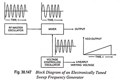
Sweep Frequency Generator – Block Diagram and its Workings
Sweep Frequency Generator - Block Diagram and its Workings: A Sweep Frequency Generator is a special type of signal generator which generates a sinusoidal output whose frequency is automatically varied or swept between two selected frequencies.…
Comments Off on Sweep Frequency Generator – Block Diagram and its Workings
November 3, 2022