Semiconductor Diode Specifications:
Diode Data Sheets – To select a suitable diode for a particular application, the data sheets, or Semiconductor Diode Specifications, provided by device manufacturers must be consulted. Portions of typical diode data sheets are shown in Fig. 2-21 .
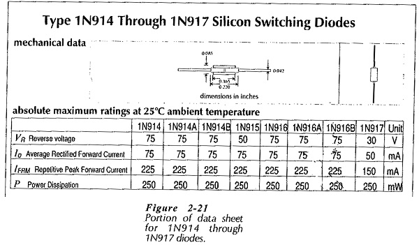
Most data sheets start off with the device type number at the top of the page, such as 1N914 through 1N917, or 1N5391 through 1N5399. The I (one) in the type number signifies a one-junction device; a diode. A short descriptive title follows the type number; for example, silicon switching diode, or silicon rectifier. Mechanical data is also given, usually in the form of an illustration showing the package shape and dimensions. The maximum ratings at 25° are then listed, (see Fig. 2-21).
The maximum ratings are the maximum voltages, currents, etc., that can be applied without destroying the device. It is very important that these ratings not be exceeded, otherwise failure of the diode is quite likely. For reliability, the maximum ratings should not even be approached. If a diode is to survive a 50 V reverse bias, one that has a 75 V peak reverse voltage should be selected. If the diode peak forward current is to be 100 mA, use a device that can handle 150 mA. It also is important to note that the maximum ratings must be adjusted downward for operation at temperatures greater than 25°C.
A list of other electrical characteristics for the device normally follows the maximum ratings. An understanding of all the parameters specified on a data sheet will not be achieved until the data sheets have been consulted frequently.
However, some of the most important parameters are considered below:
VR or VRRM – Peak reverse voltage, (also termed peak inverse voltage, and DC blocking voltage):
This is the maximum reverse voltage that may be applied across the diode.
Io or IF(AV) – Steady-state forward current:
The maximum current that may he passed continuously through the diode.
IFSM – Non-repetitive peak surge current:
This current may be passed for a specified time period. The surge current is very much higher than the normal maximum forward current. It is a current that may be allowed flow briefly when a circuit is first switched on.
IFRM – Repetitive peak surge current:
Peak current that may be repeated over and over again; for example, during each cycle of a rectified waveform.
VF – Static forward voltage drop:
The maximum forward volt drop for a given forward current and device temperature.
P – Continuous power dissipation at 25°C:
The maximum power that the device can safely dissipate continuously in free air. This rating must be downgraded at higher temperatures.
Low-Power Diodes:
The data sheet portion in Fig. 2-21 identifies the IN914 to 1N917 devices as switching diodes. The average rectified forward current is listed as 75 mA (except for the 1N917). Maximum reverse voltage ranges from 30 V to 75 V. Thus, these diodes are intended for relatively low-current, low-voltage applications, in which they may be required to switch rapidly between the on and off states.
Rectifier Diodes:
It is seen that the 1N4000 range of rectifiers can pass an average forward current of 1A, and that the 1N5390 range can pass 1.5 A. Both types have maximum reverse voltages ranging from 50 V to 1000 V. Unlike the case of the switching diodes, the reverse recovery time is not listed on the rectifier data sheet. Rectifier diodes are generally intended for low-frequency applications (60 Hz to perhaps 400 Hz) in which switching time is not important.