Reach of Distance Relay
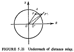
Reach of Distance Relay: A distance relay is set to operate up to a particular value of impedance; for an impedance greater than this set value the relay should not operate. This impedance, or the…
Amplitude Detection Process: Amplitude Detection - The process of demodulation demands that the modulated wave has some definite average value and the carrier wave is separated out. Hence in demodulation of an AM wave two…
Pressure Inductive Transducer: Pressure Inductive Transducer - A simple, arrangement, wherein a change in the inductance of a sensing element is produced by a pressure change, is given in Fig. 13.22. Here the pressure acting…
Class A Power Amplifiers (Direct Coupled with Resistive Load): A class A power amplifiers is defined as a power amplifier in which output current flows for the entire cycle (360°) of the input signal, as…
Analysis of Unsymmetrical Faults: In the Analysis of Unsymmetrical Faults, the following assumptions will be made : The generated e.m.f. system is of positive sequence only. No current flows in the network other than due…
Nodal Analysis Examples: Nodal Analysis Examples - we discussed simple circuits containing only two nodes, including the reference node. In general, in a N node circuit, one of the nodes is chosen as reference or…
Transfer Function or Network Function: Every network is designed to produce a particular output, when input is applied to it. The network performance is judged by studying its output for the applied input. The output…
Reverse Bias PN Junction: When an external bias voltage is applied to a pn-junction, positive to the n-side and negative to the pride, electrons from the n-side are attracted to the positive terminal, and holes…
Common Source Power Amplifier Using an Op Amp Driver Stage: Basic Circuit Operation - The Class-AB MOSFET Power Amplifier with OP Amp Driver Stage circuit in Fig. 18-45(a) consists of an operational amplifier (A1), two…
Franklin Oscillator Circuit Diagram: A simple L-C oscillator, called the Franklin oscillator and its circuit diagram is shown in Fig. 21.12. Here two CE amplifier stages are employed to provide 360° phase shift from input to…