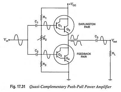
Quasi Complementary Push Pull Amplifier
Quasi Complementary Push Pull Amplifier: In practical power amplifier circuits, it is preferable to employ NPN transistors for both high-current output devices. As the push-pull connection needs complementary devices, a PNP high power transistor is…
Comments Off on Quasi Complementary Push Pull Amplifier
November 22, 2022