Schmitt Trigger Circuit Diagram
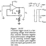
Schmitt Trigger Circuit Diagram: Inverting Schmitt Trigger - A Schmitt Trigger Circuit Diagram is a fast-operating voltage level detector. When the input voltage arrives at a level determined by the…
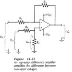
Differential Amplifier Circuit Operation: A Differential Amplifier Circuit Operation amplifies the difference between two inputs. The circuit shown in Fig. 14-23 is a combination of inverting and noninverting amplifiers. Resistors…
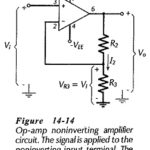
Non Inverting Amplifier Theory: Direct-Coupled Noninverting Amplifier - The Non Inverting Amplifier Theory circuit in Fig. 14-14 behaves similarly to a voltage follower circuit with one major difference. Instead of…
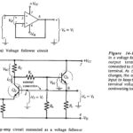
Voltage Follower Circuit Diagram: Direct-Coupled Voltage Follower - The IC operational amplifier can be employed for an infinite variety of applications. The very simplest application is the direct-coupled Voltage Follower…
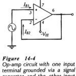
Biasing Bipolar Op Amp Circuit: Biasing Bipolar Op Amp Circuit - Like other electronic devices, operational amplifiers must be correctly biased if they are to function properly. As already discussed,…
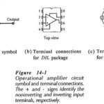
Integrated Circuit Operational Amplifier: Circuit Symbol and Packages - Figure 14-1(a) shows the triangular circuit symbol for an Integrated Circuit Operational Amplifier (op-amp). As illustrated, there are two input terminals,…
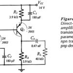
Two Stage Direct Coupled BJT Amplifier Circuit: The Two Stage Direct Coupled BJT Amplifier Circuit in Fig. 13-17 is reproduced from Fig. 12-22, and modified to include feedback components RF1Â and…
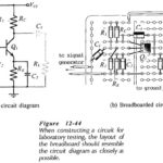
Amplifier Testing: Preparation - Transistor Amplifier Testing and other circuits should be tested in a methodical fashion; otherwise the results obtained may be useless. The circuit should first be carefully…