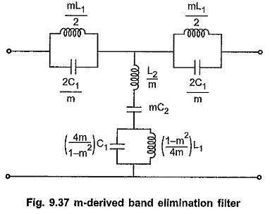
m Derived Band Stop Filter
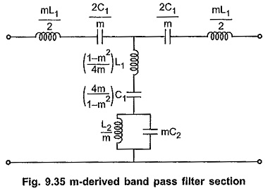
m Derived Band Stop Filter: The m Derived Band Stop Filter can be derived from the prototype band elimination filter section in the exactly same way as the m-derived band pass filter. The m Derived…
Comments Off on m Derived Band Stop Filter
November 13, 2019