Filters in Network Analysis

Chebyshev Approximation

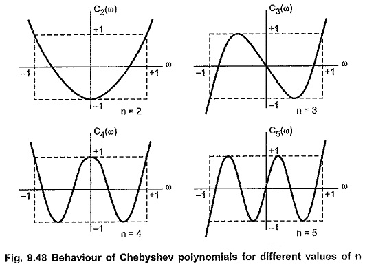
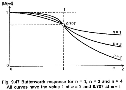
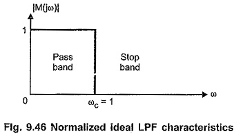
Chebyshev Approximation: Chebyshev Approximation – In the earlier section, we have studied that the Butterworth approximation is the best at ω = 0. But as we move towards cut-off frequency, ωc = 1, approximation becomes poorer. It departs from ideal characteristics. Let us consider an approximation which “ripples” about the normalized magnitude, unity, in the pass […]

Chebyshev Approximation Read More »

Butterworth Approximation

Butterworth Approximation: Butterworth Approximation – In low-pass filter design, we have to assume that all transmission zeros of the system function are at infinity. Then the magnitude function in general form can be written as, Where k is called as dc gain constant as it is the magnitude at ω = 0. f (ω2) is

Butterworth Approximation Read More »

Composite Filters in Network Analysis

Composite Filters in Network Analysis: Composite Filters in Network Analysis – In prototype filter sections, the attenuation characteristic is not very sharp in the attenuation band as it is expected. This drawback can be overcome by using m-derived filter sections which are derived from respective prototype filter sections. But it is observed that in the

Composite Filters in Network Analysis Read More »

m Derived Band Stop Filter

m Derived Band Stop Filter: The m Derived Band Stop Filter can be derived from the prototype band elimination filter section in the exactly same way as the m-derived band pass filter. The m Derived Band Stop Filter section is as shown in the Fig. 9.37. The relationship between frequency of infinite attenuation (f1∞ ,

m Derived Band Stop Filter Read More »

m Derived Band Pass Filter

m Derived Band Pass Filter: We can obtain m Derived Band Pass Filter if the prototype band pass filter is simplified according to the network in the Fig. 9.35 which has been used to obtain m-derived low pass and high pass sections. The T section in each case will have a shunt impedance, Z2/m +

m Derived Band Pass Filter Read More »

m Derived High Pass Filter

m Derived High Pass Filter: The m Derived High Pass Filter T and π sections are as shown in the Fig. 9.32 (a) and (b). Consider that the shunt arm of the T section resonates at a frequency of infinite attenuation i.e. f∞ which is selected just below cut-off frequency fc. The frequency of resonance is

m Derived High Pass Filter Read More »

m Derived Low Pass Filter

m Derived Low Pass Filter: The m Derived Low Pass Filter T and π sections are as shown in the Fig. 9.29 (a) and (b) respectively. Consider that the shunt arm of T section resonates at the frequency of infinite attenuation i.e. f∞, which is selected just above cut-off frequency fc. The frequency of resonance

m Derived Low Pass Filter Read More »

m Derived Filters

m Derived Filters: m Derived Filters – The first disadvantage of prototype filter sections can be overcome by connecting two or more prototype sections of same type (either all T type or all π type) in cascade. In such a cascade connection, attenuation to the frequencies in pass band remains zero ideally, but attenuation to

m Derived Filters Read More »

Scroll to Top