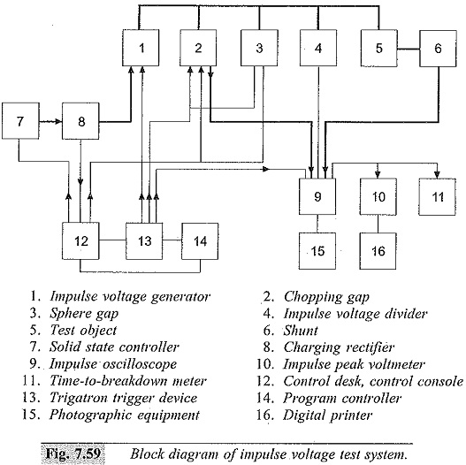
Impulse Voltage Test System
Impulse Voltage Test System: It is extremely difficult to control and adjust the Impulse Voltage Test System wave shapes for different load conditions as in the case of large capacitive loads, very low inductors or…
Comments Off on Impulse Voltage Test System
July 17, 2018