Impulse Voltage Test System:
It is extremely difficult to control and adjust the Impulse Voltage Test System wave shapes for different load conditions as in the case of large capacitive loads, very low inductors or coils, transformers with high inductance and capacitance. Further whenever the tests require comparison of test records, the resolution and uncertainty in measurements will affect the test results and the recorders should be capable of detecting even small deviations or changes.
Stringent conditions are imposed on the measuring systems, such as in the case of calibrations, diagnostic procedures, and transfer function analysis (e.g. as in transformer testing and fault diagnostics).
A modern Impulse Voltage Test System measuring and analysing system consists of a multichannel digital control and recording systems with 32 bit microprocessor controller recorder and analyser. The inputs from the measuring voltage dividers, current shunts, etc. are fed through a cable transmission system and A- D converter.
The control signals are fed to the charging unit, the trigger gaps of impulse generator, to chopping gaps, etc. Preset operations can be performed from the controller. Variable memory depths up to or more than 128 kilo data points are available.
Common Impulse Voltage Test System shapes can be analysed automatically for such computations, such as
(i) getting difference function of two waves
(ii) the Fourier analysis and FFT depicting the original wave in time domain and its Fourier transform in frequency domain
(iii) Transfer function, i.e. the ratio of neutral current to test voltage ratio in frequency domain, and
(iv) the coherence function such as comparison of impulse wave at reduced test level and at full voltage level etc.
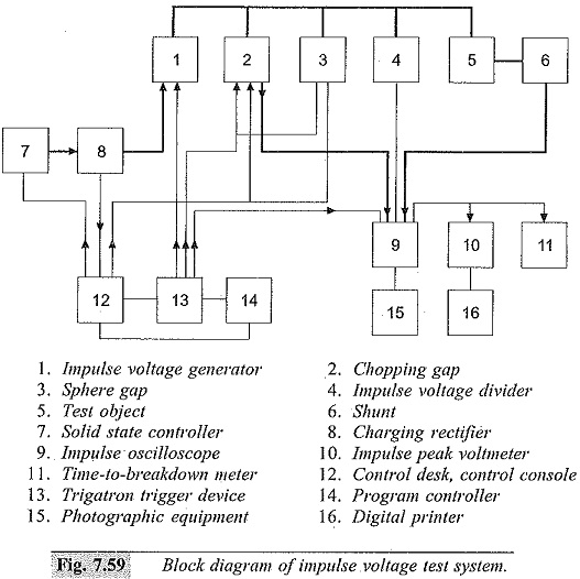
The software is normally available in common PC operating systems such as MS WINDOWS. Typical schematic diagram of a test and analyzing system is shown in Fig. 7.59.