Impulse measurements using Multiple Shield Enclosures and Signal Cable:
Multiple Shield Enclosures – It is essential that leads, layout, and connections from the signal sources to the CRO are to be arranged such that the induced voltages and stray pick-ups due to electromagnetic interference are avoided. For slowly varying signals, the connecting cables behave as either capacitive or inductive depending on the load a the end of the cable. For fast rising signals, however, the cables have to be accounted as transmission lines with distributed parameters.
A travelling wave or signal entering such a cable encounters the surge impedance of the cable. To avoid unnecessary reflections at the cable ends, it has to be terminated properly by connecting a resistance equal to the surge impedance of the cable. In cables, the signal travels with a velocity less than that of light which is given by:
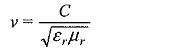
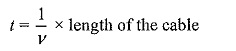
where C = 3 x 10⁸ m/s and εr and μr. are the relative permittivity and relative permeability respectively of the cable meateials. Therefore the cable introduces a finite propagation time
Measuring devices such as oscilloscopes have fmite input impedance, usually about 1 to 10 MΩ resistance in parallel with a 10 to 50 pF capacitance. This impedance at high frequencies (f ≈ 100 MHz) is about 80 Ω and thus acts as a load at the end of a surge cable. This load attenuates the signal at the CRO end.
Cables at high frequencies are not lossless transmission lines. Because of the ohmic resistance loss in the conductor and the dielectric loss in the cable material, they introduce attenuation and distortion to the signal. Cable distortion has to be eliminated as far as possible.
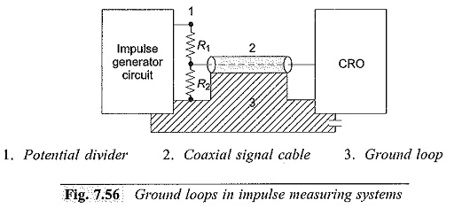
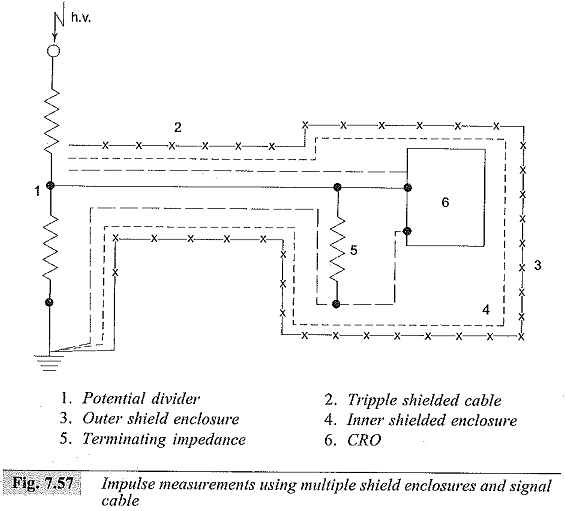
Cable shields also generate noise, voltages due to ground loop currents and due to the electromagnetic coupling from other conductors. In Fig. 7.56, the ground loop currents and their path is indicated. To eliminate these noise voltage multiple shielding arrangement as shown in Fig. 7.57 may have to be used.
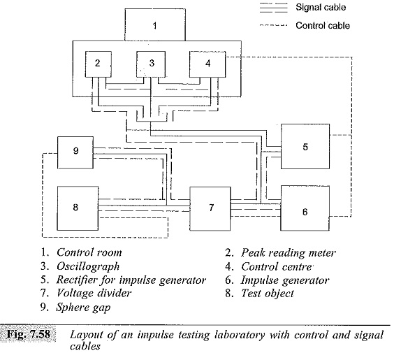
Another important factor is the layout of power and signal cables in the impulse testing laboratories. Power and interconnecting cables should not be laid in a zig-zag manner and should not be cross-connected. All power cables and control cables have to be arranged through earthed and shielded conduits.
A typical schematic layout is shown in Fig. 7.58. The arrangement should provide for branched writing from the cable tree and should not form loops. Where environmental conditions are so severe that true signal cannot be obtained with all countermeasures, electro-optical techniques for transmitting signal pulses may have to be used.