Real Transformer On Load Condition | Equivalent Circuit:
Figure 3.11 shows a Real Transformer On Load Condition. Both the primary and secondary have finite resistances R1 and R2 which are uniformly spread throughout the winding; these give rise to associated copper (I2R) losses. While a major part of the total flux is confined to the core as mutual flux Φ linking both the primary and secondary, a small amount of flux does leak through paths which lie mostly in air and link separately the individual windings.
In Fig. 3.11 with primary and secondary for simplicity assumed to be wound separately on the two legs of the core, leakage flux Φl1 caused by primary mmf I1N1 links primary winding itself and Φl2 caused by I2N2 links the secondary winding, thereby causing self-linkages of the two windings. It was seen from earlier section that half the primary and half the secondary is wound on each core leg. This reduces the leakage flux linking the individual windings. In fact it can be found by tracing flux paths that leakage flux is now confined to the annular space between the halves of the two windings on each leg.
In shell-type construction, the leakage will be still further reduced as LV and HV pancakes are interleaved. Theoretically, the leakage will be eliminated if the two windings could be placed in the same physical space but this is not possible; the practical solution is to bring the two as close as possible with due consideration to insulation and constructional requirements. Shell-type construction though having low leakage is still not commonly adopted. Actually some of the leakage flux will link only a part of the winding turns. It is to be understood here that Φl1 and Φl2 are equivalent leakage fluxes linking all N1 and N2 turns respectively.

As the leakage flux paths lie in air for considerable part of their path lengths, winding mmf and its self-linkage caused by leakage flux are linearly related in each winding; therefore contributing constant leakage inductances (or leakage reactances corresponding to the frequency at which the transformer is operated) of both primary and secondary windings. These leakage reactances are distributed throughout the winding though not quite uniformly.
Both resistances and leakage reactances of the transformer windings are series effects and for low operating frequencies at which the transformers are commonly employed (power frequency operation is at 50 Hz only), these can be regarded as lumped parameters. The Real Transformer On Load Condition of Fig. 3.11 can now be represented as a semi-ideal transformer having lumped resistances R1 and R2 and leakage reactances symbolized as Xl1 and Xl2 in series with the corresponding windings as shown in Fig. 3.13.
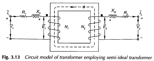
The semi-ideal transformer draws magnetizing current to set up the mutual flux Φ and to provide for power loss in the core; it, however, has no winding resistances and is devoid of any leakage. The induced emfs of the semi-ideal transformer are E1 and E2 which differ respectively from the primary and secondary terminal voltages V1 and V2 by small voltage drops in winding resistances and leakage reactances (R1, Xl1 for primary and R2, Xl2 for secondary). The ratio of transformation is
![]()
because the resistances and leakage reactance of the primary and secondary are so small in a transformer that E1 ≈ V1 and E2 ≈ V2.
Equivalent Circuit of Transformer on Load:
In Fig. 3.13 the current I1 flowing in the primary of the semi-ideal transformer can be visualized to comprise two components as below:
- Exciting current I0 whose magnetizing component Im creates mutual flux Φ and whose core-loss component I1, provides the loss associated with alternation of flux.
- A Transformer On Load component I′2 which counterbalances the secondary mmf I2N2 so that the mutual flux remains constant independent of load, determined only by E1
![]()
where
![]()
The exciting current I0 can be represented by the circuit model of Fig. 3.7 so that the semi-ideal transformer of Fig. 3.13 is now reduced to the true ideal transformer. The corresponding circuit (equivalent circuit) modelling the behavior of a Real Transformer On Load Condition is drawn in Fig. 3.14(a) wherein for ease of drawing the core is not shown for the ideal transformer.

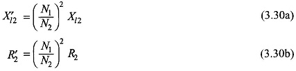
The impedance (R2 + jXl2) on the secondary side of the ideal transformer can now be referred to its primary side resulting in the equivalent circuit of Fig. 3.14(b) wherein
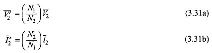
The load voltage and current referred to the primary side are
Therefore there is no need to show the ideal transformer reducing the transformer equivalent circuit to the T-circuit of Fig. 3.14(c) as referred to side 1. The Equivalent Circuit of Transformer on Load can similarly be referred to side 2 by transforming all impedances (resistances and reactances), voltages and currents to side 2. It may be noted here that admittances (conductances and susceptances) are transformed in the inverse ratio squared in contrast to impedances (resistances and reactances) which as already shown and transform in direct ratio squared. The equivalent circuit of Fig. 3.14(c) referred to side 2 is given in Fig. 3.14(d) wherein
![]()
With the understanding that all quantities have been referred to a particular side, a superscript dash can be dropped with a corresponding equivalent circuit as drawn in Fig. 3.14(e).
In the equivalent circuit of Fig. 3.14(c) if Gi is taken as constant, the core-loss is assumed to vary as E21 or Φ2max f2 (Eq. (3.6)). It is a fairly accurate representation as core-loss comprises hysteresis and eddy-current loss expressed as (KhΦ1.6max f + KeΦ2max f2). The magnetizing current for linear B-H curve varies proportional to Φmax ∞ E1/f. If inductance (Lm) corresponding to susceptance Bm is assumed constant,
![]()
It therefore is a good model except for the fact that the saturation effect has been neglected in which case Bm would be a nonlinear function of E1/f. It is an acceptable practice to find the shunt parameters Gi, Bm at the rated voltage and frequency and assume these as constant for small variations in voltage and frequency.
The passive lumped T-circuit representation of a transformer discussed above is adequate for most power and radio frequency transformers. In transformers operating at higher frequencies, the inter winding capacitances are often significant and must be included in the equivalent circuit.
The Equivalent Circuit of Transformer on Load given here is valid for a sinusoidal steady-state analysis. In carrying out transient analysis all reactances must be converted to equivalent inductances.
The Equivalent Circuit of Transformer on Load developed above can also be arrived at by following the classical theory of magnetically coupled circuits. The above treatment is, however, more instructive and gives a clearer insight into the physical processes involved.