Wein Bridge Oscillator using Op Amp:
The Wein bridge is an ac bridge that balances only at a particular supply frequency. In the Wein Bridge Oscillator using Op Amp (Fig. 16-10), a Wein bridge circuit is used as a feedback network between the amplifier output and input. The bridge is made up of all of the resistors and capacitors. The operational amplifier together with resistors R3 and R4 constitute a noninverting amplifier. The feedback network from the amplifier output to its noninverting input terminal is made up of components C1, R1, C2 and R2.
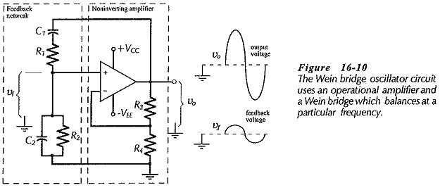
At the balance frequency of the Wein bridge, the feedback voltage is in phase with the amplifier output. This (in-phase) voltage is amplified to reproduce the output. At all other frequencies, the bridge is off balance; that is, the feedback and output voltages do not have the correct phase relationship to sustain oscillations. The Barkhausen requirement for zero loop phase shift is fulfilled in this circuit by the amplifier and feedback network both having zero phase shift at the oscillation frequency.
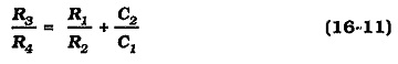
Analysis of the bridge circuit shows that balance is obtained when two equations are fulfilled:
and,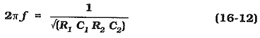
If R1C1 = R2C2, Eq. 16-12 yields,
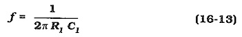
For simplicity, the components are often selected as, R1 = R2 and C1 = C2, causing Eq. 16-11 to give,
![]()
In this case, the amplifier closed-loop gain is, ACL = 3.
Sometimes it is preferable to have an amplifier voltage gain substantially greater than 3, then the relationship between the component values is determined by Equations 16-11 and 16-12.
Design of a Wein bridge oscillator can be commenced by selecting a current level for each arm of the bridge. This should be much larger than the op-amp input bias current. Resistors R3 and R4 can then be calculated using the estimated output voltage and the closed-loop gain. After that, the other component values can be determined from the above equations.
An alternative design approach is to start by selecting a convenient value for the smallest capacitor in the circuit. The other component values are then calculated from the equations.