Relative Stability from the Nyquist Plot:
Relative Stability from the Nyquist Plot – The considerations discussed above provide information about the absolute stability of the system, i.e., whether the system is stable or not. An equally important system behaviour to be considered is the relative stability. The relative stability is indicative of how various poles of the system affect the transient behaviour of a system, in other words, how oscillatory the transient behaviour of the system is. Because of the energy storage elements of the system, the system has so-called time constants and it cannot follow the input instantaneously. It exhibits a transient behaviour which dies down in a stable system. A practical system has damped oscillations before reaching the new steady-state behaviour. This behaviour of the system can be identified by the term relative stability.
The function of a closed loop system can be used to ascertain the relative stability (or degree of stability) of the system, besides its absolute stability. This feature of the system is revealed by the nearness of the polar plot to (-1, 0) point. If the locus is very close to the point, the system is very close to instability and the transient response is oscillatory. The damping ratio of the system decreases. On the other hand if the locus is away from (-1, 0) the system has more damping and less oscillatory behaviour and has better stability conditions.
The nearness of the polar plot, which reveals the relative stability of the system, is characterised by phase margin and gain margin. These definitions are used with simple shapes of locus which cross the x-axis only once. For complex shapes these are ambigious.
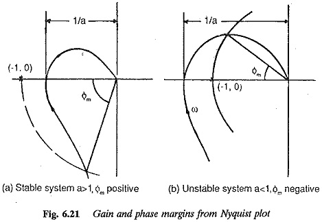
The gain margin of a system is used to describe the nearness of the point of intersection of the locus and the x-axis to (-1, 0) point. Referring to Fig. 6.21 a is referred to as gain margin. For minimum phase stable system a < 1 and unstable systems a > 1. The gain margin a is the reciprocal of the gain of the system (|G(jω)|) at the frequency at which the locus cuts the x-axis or has a phase angle of —180°. This frequency is the phase cross-over frequency. Smaller the gain of the system at the phase cross-over frequency, more stable is the system, or better is the system with respect to relative stability. As the gain (at phase cross-over) increases, the locus comes nearer to (-1, 0) and the system tends to be less stable. For a stable system the gain margin must be positive, and negative for unstable ones. In other words the gain margin of a stable system indicates by how much the gain must be increased before the system is unstable. For unstable systems it indicates how much it must be reduced to make the system stable.
The gain margin of first and second order systems is infinite as their polar plots do not cross the x-axis. Therefore, theoretically speaking they cannot become unstable. In practice these systems may have small time lags which are neglected in the derivation of transfer functions. When these are taken into consideration the systems may become unstable. However, increase of gain constant brings the locus nearer to the point (-1, 0) making the transient response more oscillatory. This is depicted for a second order system in Fig. 6.20 which gives the Nyquist locus and transient response of the system for different values of gain constant.
The phase margin of the system Φm is also used to describe the closeness of the Nyquist locus to (-1, 0) or in otherwords to describe the relative stability. The phase margin can be defined as the angle by which the locus may be rotated in the clockwise direction so that the locus passes through the point (-1, 0). The phase margin is, therefore, the angle enclosed by the negative real axis and the line joining the origin and the point of intersection of the locus and the unit circle drawn with the centre as the origin. Referring to Fig. 6.21 the phase margin
![]()
where Φ0 is the phase angle of the open loop transfer function when its magnitude is unity. The frequency at which the magnitude is unity is called the gain cross over frequency. The phase margin is the additional phase lag at the gain cross-over frequency to make the locus pass through the point (-1, 0), so that the system is on the verge of instability. From the definition, it is clear that the phase margin (Φm) is positive for stable systems. As it approaches zero, the system becomes less stable and its transient response becomes oscillatory. When Φm is zero the system is on the verge of instability. The value of Φm is negative (< 0) for unstable systems.
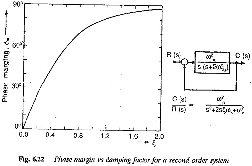
The specification of gain or phase margin above does not indicate the degree of stability or relative stability of the system. The relative stability of the system is decided by the specification of both the margins. For a system to have adequate stability some minimum values of these margins have to be specified, i.e. a > 1.5 and cbiu > 45°. These minimum values may be set depending upon the degree of stability required. They ensure the stability of a system against the variations in the parameters of the system or components of the system, e.g., open loop gain constant or time constants. These margins being a measure of the closeness of the plot to (-1, 0) indicate the effective damping ratio of the system. Closer the response to (-1, 0), lesser is the effective damping ratio. The phase margin and damping ratio are very closely related, as shown in Fig. 6.22. A phase margin of 60° corresponds to a damping ratio of 0.6. Even though the gain margin can also be related to the damping ratio, phase margin is the better estimate of damping ratio; since it influences the transient overshoot more than gain margin.
These margins can therefore be used as design criteria. They offer a means of adjusting the gain and time constants of the system to obtain the required behaviour. The design of various controllers to improve the stability performance is based on providing specified values of phase and gain margins.
The above discussion is applicable to systems which are absolutely stable. It is necessary to note that the stability condition for non-minimum phase functions is satisfied only if the Nyquist plot encircles (-1, 0). For these systems therefore, the phase and gain margins are negative.