Armature Winding in DC Machine:
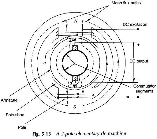
With reference to the single-coil elementary Armature Winding in DC Machine of Figs 5.13 and 5.14(a) which shows the B-wave of the machine relative to the elementary full-pitched coil,
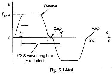
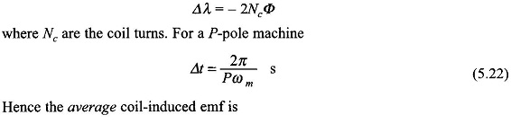
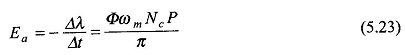
Let![]() Consider that the coil is lying in the interpolar region so that the full flux/pole (Φ) links it positively. Let it now move through one pole-pitch (π rad elect.) in time Δt so that its flux linkages reverse in sign. The change in flux linkages during this movement is
Consider that the coil is lying in the interpolar region so that the full flux/pole (Φ) links it positively. Let it now move through one pole-pitch (π rad elect.) in time Δt so that its flux linkages reverse in sign. The change in flux linkages during this movement is
 The dc machine armature is always wound with 2-layer winding forming a closed circuit. The coils are suitably connected to the commutator segments made of copper, insulated from each other and from the shaft and formed into a cylinder. The current from the armature winding is tapped through brushes placed on the commutator periphery, 180° elect. apart. The alternate brushes are of opposite polarity and all the brushes of one polarity are connected in parallel resulting in two armature terminals. This arrangement causes the closed armature winding to form a series-parallel circuit.
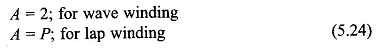
The dc voltage between the brushes of opposite polarity is the sum of the average voltages of series turns between the brushes, each turn having the same average voltage. The number of parallel paths depends upon the type of Armature Winding in DC Machine wave and lap type and are
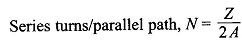
 Let the machine be wound with Z conductors (a conductor is the active part of the side of a turn). Since two conductors form a turn,
 Using Eq. (5.23), the armature emf which equals the parallel path emf is given by
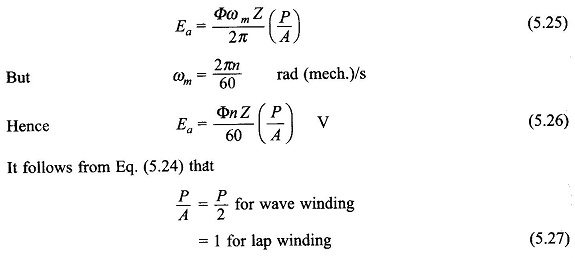
Since P has a minimum value of 2, the wave winding will have a larger armature emf than a lap winding for the same values of Φ, n and Z.
The details of the dc machine winding, where the brushes are placed on the commutator and how the parallel paths are formed.
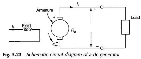 The circuit schematic (circuit model) of a dc generator is drawn in Fig. 5.23. As the current in the field and armature circuits are dc, the circuit inductances do not play any role. The armature circuit has a voltage Ea induced in it by rotation of armature in the flux/pole Φ as per the relationship of Eq. (5.25). When the armature feeds current to the external circuit (the load), there is a voltage drop IaRa in the armature circuit, where Ra is the effective resistance of the armature. The Kirchoff voltage law applied to the armature circuit yields
![]() where Vt is the voltage at generator terminals. This equation is usually written as
where Vt is the voltage at generator terminals. This equation is usually written as
![]()