Base Bias in BJT:
Circuit Operation and Analysis – The transistor bias arrangement shown in Fig. 5-12 is known as Base Bias in BJT and also as fixed current bias. The base current is a constant quantity determined by supply voltage VCC and base resistor RB. Because VCC and RB are constant quantities. IB remains fixed at a particular level. Unlike some other bias circuits, the base current in a Base Bias in BJT circuit is not affected by the transistor current gain.
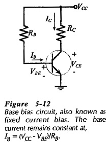
From Fig. 5-12, the voltage drop across RB is (VCC – VBE) , and the base current is,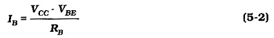
In Eq. 5-2 the base-emitter voltage (VBE) is taken as 0.7 V for a silicon transistor, and as 0.3 V for a germanium device.
The transistor collector current is calculated as,
![]()
The collector current is now used with Eq. 5-1 (VCE = VCC – ICRC) to calculate the collector-emitter voltage. Thus, when the supply voltage and component values are known, a Base Bias in BJT is easily analysed to determine the circuit current and voltage levels.
Effect of hFE(max) and hFE(min)
When the transistor dc current gain is known, it is quite easy to determine the circuit bias conditions. However, In practice the precise current gain of each transistor is normally not known. The transistor is usually identified by its type number, and then the maximum and minimum values of current gain can be obtained from the manufacturer’s data sheet. In circuit analysis it is sometimes convenient to use a typical hFE value.
Base Bias Using pnp Transistor:
All of the Base Bias in BJT circuits discussed so far use npn transistors. Figure 5-16 shows circuits that use pnp transistors. In Fig. 5-16(a) note that the voltage polarities and current directions are reversed compared to npn transistor base bias circuits. Because it is normal to show the supply voltage with the positive terminal uppermost, the circuit of Fig. 5-16(a) is redrawn in Fig. 5-16(b). This is the way that the circuit would usually be shown.
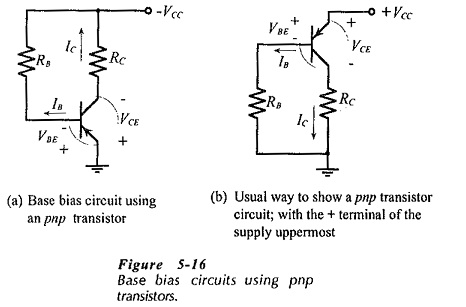
Equations 5-2, and 5-3 can be applied for analyzing pnp transistor Base Bias in BJT circuit exactly as for npn transistor circuits.