Types of Filters in Electronics:
Types of filters in electronics may be of any physical form—electrical, mechanical, pneumatic, hydraulic, acoustical, etc. The most commonly used filters are of the electrical type. Types of filters in electronics may be classified as follows.
- Low Pass Filter
- High Pass Filter
- Band Pass Filter
- Band Stop Filter
- All Pass Filter
Consider a basic configuration of an electrical filter shown in Fig. 15.1 (b). The source is sinusoidal, of variable frequency. The filter circuit may be so designed that some frequencies are passed from the input to the output of the filter with very little attenuation (pass band) while others are greatly attenuated (attenuation band).
The responses of types of filters in electronics are shown in Fig. 15.2. These are ideal responses that cannot be achieved in actual practice.
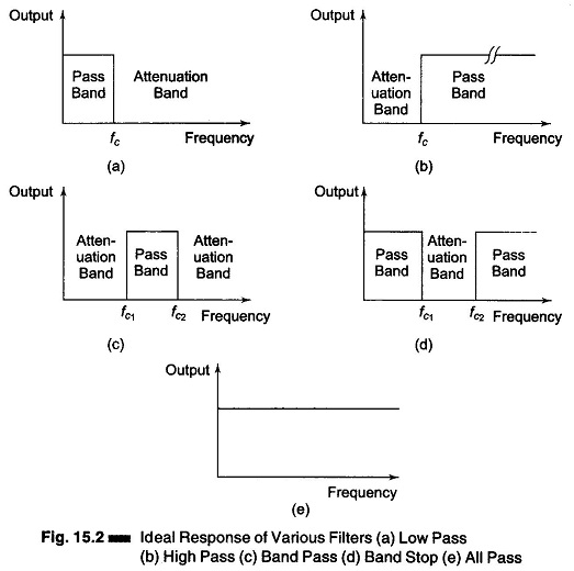
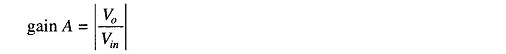
The ideal response of a low pass filter is shown in Fig. 15.2 (a). The voltage gain is given by output/input.
Hence
This gain is constant over a frequency range starting from zero to a cut off frequency fc. The output of any signal having a frequency greater than fc will be attenuated, i.e. there will be no output voltage for frequencies greater than the cutoff frequency fc. Hence output will be available faithfully from 0 to fc with constant gain, and is zero from fc onward.
The characteristics of a High Pass filter are shown in Fig. 15.2 (b). The HP filter has a zero gain starting from zero to a frequency fc, the cut off frequency. Above this cutoff frequency, the gain is constant and equal to A. Hence signal of any frequency beyond fc will be faithfully reproduced with a constant gain, and frequencies from 0 to fc. will be attenuated.
The band pass filter characteristics are shown in Fig. 15.2 (c). It faithfully reproduces signals falling between fc1 and fc2, while signals between 0 and fc1, and frequencies greater than fc2 are attenuated. There is an output corresponding to signals having frequencies between fc1 and fc2, but no output for signals having frequencies below fc1 and above fc2. Hence this filter passes a band of frequencies.
Figure 15.2(d) shows the characteristics of a band stop filter. This filter attenuates a particular band of frequencies from fc1 to fc2, while passing all frequencies between 0 and fc1 and fc2 onwards. This filter is also called a notch filter.
Figure 15.2(e) shows the characteristics of an all pass filter. In this filter all frequencies are passed without attenuation. The important feature of this filter is that it provides predictable phase shift for frequencies of different input signals. These filters are mostly used in communications.
The types of filters in electronics discussed above have ideal characteristics and a sharp cutoff. In actual practice the characteristics shown in Fig. 15.2 are not practicable in a practical filter circuit. Attenuation outside the pass band, that is in the attenuation band, is finite. The attenuation can be made sufficiently large by adding several filters in tandem. Also, it is not possible to have a pure inductor (inductor without resistance). Hence the attenuation in the pass band will not be zero. Only those characteristics of filters which can be practically realized are discussed below.
Basic Low Pass Filter:
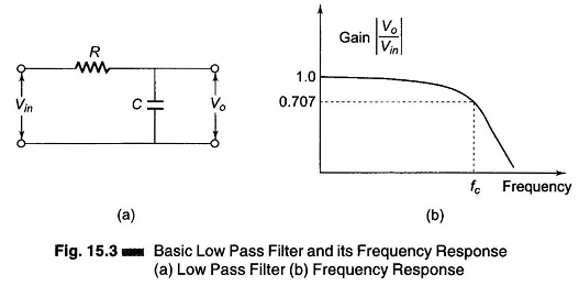
An electric low pass filter is shown in Fig. 15.3 (a). It is an RC network. At low frequencies, the capacitive reactance is very high and the capacitor circuit can be considered as open circuit. Under this condition, the output equals the input ( Vo = Vin) or voltage gain is equal to unity. At very high frequencies, the capacitive reactance is very low and the output voltage Vo is small as compared with the input voltage Vin. Hence the gain fall and drops off gradually as the frequency is increased, as shown in Fig. 15.3 (b).
The transfer function is
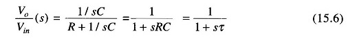
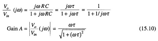
The sinusoidal transfer function of a low pass filter is
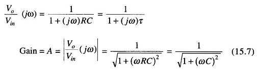
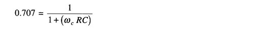
The gain drops to 0.707 at the cut off frequency ωc
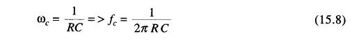
or cut off frequency
Basic High Pass Filter:
An electrical high pass filter is shown in Fig. 15.4(a). When the frequency is low, the capacitive reactance is high, hence minimum output is available and the gain is small. When the frequency is high, the capacitive reactance is small, the output equals the input and the gain approaches unity. Hence this circuit passes high frequencies while rejecting low frequencies. The response of a high pass filter is as shown in Fig. 15.4(b).
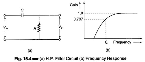
The transfer function of a high pass filter is given by
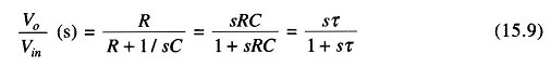
Sinusoidal transfer function of a high pass filter is