Sky Wave Propagation Frequency Range:
Sky Wave Propagation Frequency Range is the ionosphere is the upper portion of the atmosphere, which absorbs large quantities of radiant energy from the sun, becoming heated and ionised. There are variations in the physical properties of the atmosphere, such as temperature, density and composition. Because of this and the different types of radiation received, the ionosphere tends to be stratified, rather than regular, in its distribution. The most important ionising agents are ultraviolet and α, β, and γ radiation from the sun, as well as cosmic rays and meteors. The overall result, as shown in Figure 8-13, is a range of four main layers, D, E, F1 and F2, in ascending order. The last two combine at night to form one single layer.
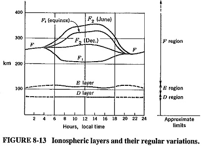
The D layer is the lowest, existing at an average height of 70 km, with an average thickness of 10 km. The degree of its ionisation depends on the altitude of the sun above the horizon, and thus it disappears at night. It is the least important layer from the point of view of HF propagation. It reflects some VLF and LF waves and absorbs MF and HF waves to a certain extent.
The E layer is next in height, existing at about 100 km, with a thickness of perhaps 25 km. Like the D layer, it all but disappears at night; the reason for these disappearances is the recombination of the ions into molecules. This is due to the absence of the sun (at night), when radiation is consequently no longer received. The main effects of the E layer are to aid MF surface-wave propagation a little and to reflect some HF waves in daytime.
The Es layer is a thin layer of very high ionization density, sometimes making an appearance with the E layer. It is also called the sporadic E layer; when it does occur, it often persists during the night also. On the whole, it does not have an important part in long-distance propagation, but it sometimes permits unexpectedly good reception. Its causes are not well understood.
The F1 layer, as shown in Figure 8-13, exists at a height of 180 km in daytime and combines with the F2 layer at night, its daytime thickness is about 20 km. Although some HF waves are reflected from it, most pass through to be reflected from the F2 layer. Thus the main effect of the F1 layer is to provide more absorption for HF waves. Note that the absorption effect of this and any other layer is doubled, because HF waves are absorbed on the way up and also on the way down.
The F2 layer is by far the most important reflecting medium for high-frequency radio waves. Its approximate thickness can be up to 200 km, and its height ranges from 250 to 400 km in daytime. At night it falls to a height of about 300 km, where it combines with the F1 layer. Its height and ionization density vary tremendously, as Figure 8-13 shows. They depend on the time of day, the average ambient temperature and the sunspot cycle (see also the following sections dealing with the normal and abnormal ionospheric variations). It is most noticeable that the F layer persists at night, unlike the others. This arises from a combination of reasons; the first is that since this is the topmost layer, it is also the most highly ionized, and hence there is some chance for the ionization to remain at night, to some extent at least. The other main reason is that although ionization density is high in this layer, the actual air density is not, and thus most of the molecules in it are ionized. Furthermore, this low actual density gives the molecules a large mean free path (the statistical average distance a molecule travels before colliding with another molecule). This low molecular collision rate in turn means that, in this layer, ionization does not disappear as soon as the sun sets. Finally, it must be mentioned that the reasons for better HF reception at night are the combination of the F1 and F2 layers into one F layer, and the virtual disappearance of the other two layers, which were causing noticeable absorption during the day.
Reflection Mechanism:
Electromagnetic waves returned to earth by one.of the layers of the ionosphere appear to have been reflected. As the ionization density increases for a wave approaching the given layer at an angle, so the refractive index of the layer is reduced. (Alternatively, this may be interpreted as an increase in the conductivity of the layer, and therefore a reduction in its electrical density or dielectric constant.)
If the rate of change of refractive index per unit height (measured in wavelengths) is sufficient, the refracted ray will eventually become parallel to the layer. It will then be bent downward, finally emerging from the ionized layer at an angle equal to the angle of incidence. Some absorption has taken place, but the wave has been returned by the ionosphere (well over the horizon if an appropriate angle of incidence was used).
Terms and Definitions:
The terminology that has grown up around the ionosphere and Sky Wave Propagation Frequency Range includes several names and expressions whose meanings are not obvious. The most important of these terms will now be explained.
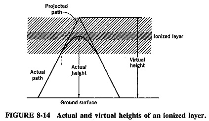
The virtual height of an ionospheric layer is best understood with the aid of Figure 8-14. This figure shows that as the wave is refracted, it is bent down gradually rather than sharply. However, below the ionized layer, the incident and refracted rays follow paths that are exactly the same as they would have been if reflection had taken place from a surface located at a greater height, called the virtual height of this layer. If the virtual height of a layer is known, it is then quite simple to calculate the angle of incidence required for the wave to return to ground at a selected spot.
The critical frequency (fc) for a given layer is the highest frequency that will be returned down to earth by that layer after having been beamed straight up at it. It is important to realise that there is such a maximum, and it is also necessary to know its value under, a given set of conditions, since this value changes with these conditions. It was mentioned earlier that a wave will be bent downward provided that the rate of change of ionization density is sufficient, and that this rate of ionization is measured per unit wavelength. It also follows that the closer to being vertical the incident ray, the more it must be bent to be returned to earth by a layer. The result of these two effects is twofold. First, the higher the frequency, the shorter the-wavelength, and the less likely it is that the change in ionization density will be sufficient for refraction. Second, the closer to vertical a given incident ray, the less likely it is to be returned to ground. Either way, this means that a maximum frequency must exist, above which rays go through the ionosphere. When the angle of incidence is normal, the name given to this maximum frequency is critical frequency; its value in practice ranges from 5 to 12 MHz for the F2 layer.
The maximum usable frequency, also a limiting frequency, but this time for some specific angle of incidence other than the normal. In fact, if the angle of incidence (between the incident ray and the normal) is θ, it follows that
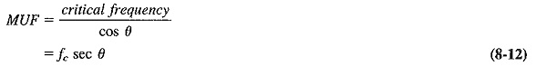
This is the so-called secant law, and it is very useful in making preliminary calculations for a specific MUF. Strictly speaking, it applies only to a flat earth and a flat reflecting layer. However, the angle of incidence is not of prime importance, since it is determined by the distance between the points that are to be joined by a sky-wave link. Thus MUF is defined in terms of two such points, rather than in terms of the angle of incidence at the ionosphere, it is defined at the highest frequency that can be used for Sky Wave Propagation Frequency Range between two given points on earth.-It follows that there is a different value of MUF for each pair of points on the globe. Normal values of MUF may range from 8 to 35 MHz, but after unusual solar activity they may rise to as high as 50 MHz. The highest working frequency between a given pair of points is naturally made less than the MUF, but it is not very much less for reasons that will be seen.
The skip distance is the shortest distance from a transmitter, measured along the surface of the earth, at which a Sky Wave Propagation Frequency Range of fixed frequency (more than fc) will be returned to earth. That there should be a minimum distance may come as a shock. One expects there to be a maximum distance, as limited by the curvature of the earth, but nevertheless a definite minimum also exists for any fixed transmitting frequency. The reason for this becomes apparent if the behaviour of a Sky Wave Propagation Frequency Range is considered with the aid of a sketch, such as Figure 8-15.
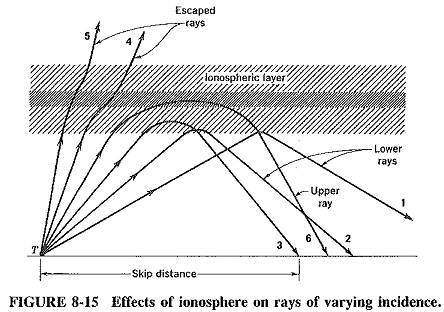
When the angle of incidence is made quite large, as for ray 1 of Figure 8-15, the Sky Wave Propagation Frequency Range returns to ground at a long distance from the transmitter. As this angle is slowly reduced, naturally the wave returns closer and closer to the transmitter, as shown by rays 2 and 3. If the angle of incidence is now made significantly less than that of ray 3, the ray will be too close to the normal to be returned to earth. It may be bent ray 4, or only slightly, as for ray 5. In either case the bending will be insufficient to return the wave, unless the frequency being used for communication is less than the critical frequency (which is most unlikely); in that case everything is returned to earth. Finally, if the angle of incidence is only just smaller than that of ray 3, the wave may be returned, but at a distance farther than the return point of ray 3; a ray such as this is ray 6 of Figure 8-15. This upper ray is bent back very gradually, because ion density is changing very slowly at this angle. It thus returns to earth at a considerable distance from the transmitter and is weakened by its passage.
Ray 3 is incident at an angle which results in its being returned as close to the transmitter as a wave of this frequency can be. Accordingly, the distance is the skip distance. It thus follows that any higher frequency beamed up at the angle of ray 3 will not be returned to ground. It is seen that the frequency which makes a given distance correspond to the skip distance is the MUF for that pair of points.
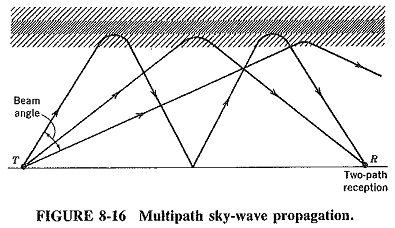
At the skip distance, only the normal, or lower, ray can reach the destination, whereas at greater distances the upper ray can be received as well, causing interference. This is a reason why frequencies not much below the MUF are used for transmission. Another reason is the lack of directionality of high-frequency antennas. If the frequency used is low enough, it is possible to receive lower rays by two different paths after either one or two hops, as shown in Figure 8-16, the result of this is interference once again.
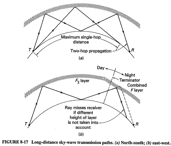
The transmission path is limited by the skip distance at one end and the curvature of the earth at the other. The longest single-hop distance is obtained when the ray is transmitted tangentially to the surface of the earth, as shown in Figure 8-17. For the F2 layer, this corresponds to a maximum practical distance of about 4000 km. Since the semi circumference of the earth is just over 20,000 km, multiple-hop paths are often required, and Figure 8-17 shows such a situation. No unusual problems arise with multihop north-south paths. However, care must be taken when planning long east-west paths to realise that although it is day “here,” it is night “there,” if “there” happens to be on the other side of the terminator. The result of not taking this into account is shown in Figure 8-17b. A path calculated on the basis of a constant height of the F2 layer will, if it crosses the terminator, undershoot and miss the receiving area as shown the F layer over the target is lower than the F2 layer over the transmitter.
Fading is the fluctuation in signal strength at a receiver and may be rapid or slow, general or frequency-selective. In each case it is due to interference between two waves which left the same source but arrived at the destination by different paths. Because the signal received at any instant is the vector sum of all the waves received, alternate cancellation and reinforcement will result if there is a length variation as large as a half-wavelength between any two paths. It follows that such fluctuation is more likely with smaller wavelengths, i.e., at higher frequencies.
Fading can occur because of interference between the lower and the upper rays of a Sky Wave Propagation; between sky waves arriving by a different number of hops or different paths; or even between a ground wave and a sky wave especially at the lower end of the HF band. It may also occur if a single sky wave is being received, because of fluctuations of height or density in the layer reflecting the wave. One of the more successful means of combating fading is to use space or frequency diversity.
Because fading is frequency-selective, it is quite possible for adjacent portions of a signal to fade independently, although their frequency separation is only a few dozen hertz. This is most likely to occur at the highest frequencies for which Sky Wave Propagation Frequency Range are used. It can play havoc with the reception of AM signals, which are seriously distorted by such frequency-selective fading. On the other hand, SSB signals suffer less from this fading and may remain quite intelligible under these conditions. This is because the relative amplitude of only a portion of the received signal is changing constantly. The effect of fading on radiotelegraphy is to introduce errors, and diversity is used here wherever possible.
Ionospheric Variations:
The ionosphere is highly dependent upon the sun, and hence its conditions vary continuously. There are two kinds of variations. The normal ones have already been described as diurnal and seasonal height and thickness changes. Abnormal variations are due mainly to the fact that our sun is a variable star.
The sun has an 11-year cycle over which its output varies tremendously. Most people are unaware of this, because light variations are slight. However, the solar output of ultraviolet rays, coronae, flares, particle radiation and sunspots may vary as much as fiftyfold over that period. The extent of solar disturbance is measured by a method of sunspot counting developed by Wolf in the eighteenth century. On this basis, a pronounced 11-year (±1 year) cycle emerges, and perhaps also a 90-year supercycle. The highest activities so far recorded were in 1778, 1871 and 1957, which was the highest ever.
The main sun-caused disturbances in the ionosphere are SIDs (sudden ionospheric disturbances, formerly known as Dellinger dropouts) and ionospheric storms. Sudden ionospheric disturbances are caused by solar flares, which are gigantic emissions of hydrogen from the sun. Such flares are sudden and unpredictable, but more likely during peak solar activity than when the sun is “quiet.” The x-ray radiation accompanying solar flares tremendously increases ionization density, right down to the D layer. This layer now absorbs signals that would normally go through it and be reflected from the F layer. Consequently, long-distance communications disappear completely, for periods up to 1 hour at a time. Studies with earth-based radioheliographs and from satellites in orbit have provided a large amount of data on solar flares, so that some short-term predictions are becoming possible. Two other points should be noted in connection with SIDs. First, only the sunlit side of the earth is affected, and second, VLF propagation is actually improved.
Ionospheric storms are caused by particle emissions from the sun, generally α and β rays. Since these take about 36 hours to reach the earth, some warning is possible after large sunspots or solar flares are noticed. The ionosphere behaves erratically during a storm, right around the globe this time, but more so in high latitudes because of the earth’s magnetic field. Signal strengths drop and fluctuate quite rapidly.
However, using lower frequencies often helps, since the highest ones are the most affected.
Finally, the sporadic E layer previously mentioned is also often included as an abnormal ionospheric disturbance. When present, it has the twin effects of preventing long-distance HF communications and permitting over-the-horizon VHF communications. The actual and virtual heights of this layer appear to be the same. This confirms the belief that the layer is thin and dense, so that actual reflection takes place.
Various national scientific bodies have ionospheric prediction programs which issue propagation notices of great value. Among them are the notices of the Central Radio Propagation Laboratory of the United States and the Ionospheric Prediction Service of the Australian Department of Science and Technology.