Transistor Tester and its characteristics:
The term Transistor Tester (or analyser) used in this text is for instruments giving quantative measurements of transistor parameters. The tester should be able to provide direct readings for at least two important measurements, such as:
- A value for the forward gain in the common emitter configuration (hFE for ac gain or hFE for dc gain), that is β gain.
- A value for collector to base leakage current, with emitter open Icbo.
The latter measurement of C to B reverse current is generally regarded as most significant to test for the ageing of a transistor. It is an comparatively difficult measurement because of the small currents involved (in μA), and because of its extreme temperature sensitivity.
A typical service type transistor and diode tester examines transistors for the following characteristics.
- Short-Circuit Test for C-E Breakdown
- Direct Measurement of Collector-Leakage Current
- Direct Current Gain Test
- Alternating Current Gain Test
- Four Terminal Parameter Test (Hybrid Parameters)
- Transistor Tester for Polarity
1. Short–Circuit Test for C–E Breakdown:
In the arrangement for the short-circuit test given in Fig. 10.18, the emitter and base terminals of the Transistor under test are tied together and a reverse voltage of 4.5 V is applied between the collector and the two leads that are connected together. Figure 10.18(a) shows an arrangement for a PNP transistor and Fig. 10.18 (b) shows an arrangement for an NPN transistor.
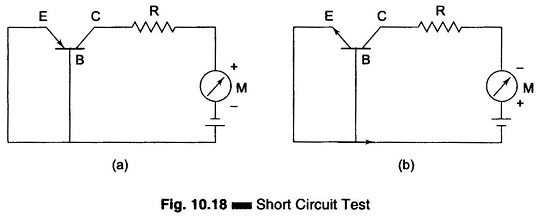
If there is a breakdown (usually from collector to emitter), the indicating meter tends to read full scale deflection. In that case, no further tests are performed on that transistor , thus avoiding possible damage to the meter circuit.
If the reading in the short position is less than the maximum allowable amount indicated on the chart, the next test for reverse current Icbo, is set up.
2. Direct Measurement of Collector–Leakage Current:
Collector-leakage current is a function of the temperature and resistivity of the material of the transistor. Excessive leakage generally occurs when the conductor surface is contaminated. Other causes of this condition are overheating, or other types of damage. This is reverse current from the collector to the base, with the emitter open, denoted Icbo. An excessive Icbo indicates a faulty transistor. The tester circuit for this test is illustrated in Fig. 10.19(a). The collector-base junction is reverse biased and the emitter is open. The ammeter (in the micro range) indicates the reverse current.
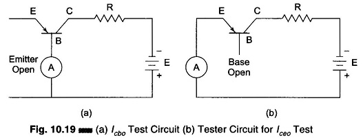
Current from the collector to the emitter with an open base is denoted Iceo .Figure 10.19(b) illustrates the circuit for this test. Iceo should be expected to be much larger than Icbo.
3. Direct Current Gain Test:
Direct current gain is a measure of the effectiveness of the base in controlling collector current. It is a useful parameter for transistors used in low frequency power, amplification, switching, and control circuits. This test is useful only if the transistor is used in a common-emitter configuration.
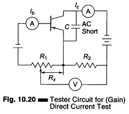
Figure 10.20 illustrates the tester circuit used for test. R1 is adjusted for a null on the voltmeter, at this point the dc gain is equal both to Ic/Ib and Rx/R2.R1 usually has a calibrated dial to provide a direct reading of dc gain.
As a transistor ages, there is a tendency for the dc gain to decrease. This causes the amplification to decrease, which leads to distortion of the signal.
4. Alternating Current Gain Test:
Alternating current gain is expressed in two different ways, depending on the type of configuration the transistor is used in. For a common-base configuration, the amplification factor is alpha (α), which is the ratio of the change in the collector current to the change in the emitter current, with the collector voltage held constant. The collector has an ac short to the base during this test.
![]()
If the transistor is in a common-emitter configuration, the amplification factor is beta β, which is the ratio of the change in collector current to the change in base current when the collector voltage is held constant. The collector has an ac short to the emitter during this test.
![]()
There is a definite relationship between alpha and beta, so that either may be calculated when the other is known.
The test circuit for measuring beta is similar to that for measuring dc gain (see Fig. 10.20). The primary difference is that the beta measurement requires an ac signal at the transistor base. The proper values of either beta or alpha are given on the manufacturer’s data sheet. The measured values should match these fairly closely, if the transistor is good.
5. Four Terminal Parameter Test (Hybrid Parameters):
A transistor may be considered as a four terminal network in order to determine the relationships between input and outputs. These relationships are referred to as hybrid (h) parameters, which are referred to in data sheets and on test instrument.
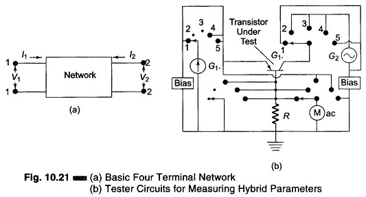
Hybrid parameters are very useful in determining the quality of a transistor. The four terminal network is shown in Fig. 10.21(a).
With this arrangement, there are two currents and two voltages to consider. If the two currents are considered as dependent variables, the resulting parameters are short-circuited parameters, and they are measured in mhos. When the two voltages are considered as dependent variables, the resulting parameters are open-circuit parameters, and they are measured in ohms. Hybrid (h) parameters are obtained by using one current and one voltage as dependent variables. The designations for the four h parameters are as follows.
- hi — input impedance with output shorted
- hr — reverse voltage ratio with input open
- hf — forward current gain with output shorted
- ho — output admittance with input open
The unit of measure for hi is ohms, and for ho is mhos. There are no units for hf and hr, since they are ratios.
The h parameters can be applied to any of the three basic amplifier configurations. An additional subscript letter is generally used to designate the type of configuration. Subscript b indicates common-base, e designates common-emitter and c denotes a common-collector.
The h parameter designations for a common emitter are hie, hre, hfe, and hoe. Alpha for a common base circuit is equal to hfb and beta in a common emitter is equal to hfe.
The tester circuit for obtaining h parameters is illustrated in Fig. 10.21(b). G1 is a calibrated current generator and G2 is a calibrated voltage generator. The ac meter is used to indirectly measure current. The switches are four ganged sections of a five position rotary switch.
Position 1 of the switch connects the calibrated current generator to the emitter of the transistor under test. The ac meter indicates I+ hf which is the ratio of the ac base current (ib) to the ac emitter current (ie)
Position 2 of the switch connects the calibrated voltage generator to the collector, and the meter indicates the output admittance, ho. The emitter is open during this measurement.
Position 3 measures hr, position 4 measures hi, and position 5 measures alpha.
6. Transistor Tester for Polarity:
This tester checks the transistor for polarity (PNP or NPN). An audible signal gives an indication of gain. This tester is illustrated in Fig. 10.22.
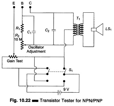
The tester can also be used as a GO/NO GO tester to match unmarked devices.