Operation of UHV Laboratory:
Operation of UHV Laboratory are designed as indoor laboratories or outdoor laboratories depending on the specific requirements. An indoor laboratory is preferred when most of the equipment testing and associated research work is carried out indoors, whereas outdoor laboratories are preferred when the electrical and mechanical parameters of the UHV transmission lines are to be experimentally determined so that the design of future lines can be based on this data. During the 1980s when the Operation of UHV Laboratory was planned in India its potential role was widely discussed–the steps involving transmission line ratings beyond 420 kV were 750-765 kV and 1100-1200. kV. There were definite indications that transmission systems at voltages greater than 420 kV would be a reality within the next 15-20 years. Further there were similar laboratories being built in Canada, USA, UK, Italy, Japan, etc. Such a facility was needed in India also to generate test data of breakdown voltages and air clearances which would be necessary to design a future transmission line. Therefore, an outdoor UHV laboratory was conceived, designed and built in India by the Central Power Research Institute to meet its future requirements.
Some salient features of this Operation of UHV Laboratory are as follows:
The Operation of UHV Laboratory is an outdoor facility except the pollution laboratory and a test hall for conducting basic research. Brief details of each of the facilities/ equipment are given below.
The UHV transmission line was built in such a way that the probable incidence of winds is nearly perpendicular to its axis. From the wind data available at the site for a period of about 10 years, it was decided to construct the line in the north—south direction. This will take full advantage of the south—east winds, which are fairly abundant from November to April and the north—west winds that are frequent from May to September, the Azimuthal orientation for the test line was fixed as north, north—east, south, south—west direction. Since wind induced conductor vibrations do not pose a serious problem in India, it was decided to have only one single phase experimental line but with two bundle conductors. This type of a line permits simultaneous comparative testing, both electrical and mechanical, on two different bundles, and also allows independent electrical and mechanical studies. Further the line can be used later, if necessary, for bi-polar HVDC studies.
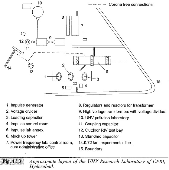
The line has an overall length of 720 m, of which, one section is the central suspension span of 360 m length and the other two sections are dead-end spans each having a length of 180 m. At present, a single phase line with 10 conductor bundles is strung to enable to study its corona performance including the RI, AN, and corona power loss when energized by a phase to ground voltage of 1050 kV. The mechanical vibration aspects of the line are also studied using the same line. The approximate layout of the Operation of UHV Laboratory is given in Fig. 11.3.
Power Frequency Testing Transformer: The power frequency testing transformer is a cascade unit having two 800 kV single phase transformers with an output voltage of 1600 kV and a maximum current of 6 A at the output terminals. The input to the transformer unit is from an 11 kV, 3-phase source through a sliding type voltage regulator whose maximum rating is 10.5 kV. The transformer winding connections can be modified to give higher short circuit currents ranging from 17 A to 47 A. Thus, this source is best suited for conducting artificial pollution tests. The full load current of 6A, although is high for a normal testing transformer, is necessary for charging the experimental transmission line. The transformer is also discharge free up to the full range of voltage output making it suitable for carrying out conducted and radiated RIV measurements. It pan also be used for conducting dielectric tests on the line component insulation rated up to 1050 kV. An additional feature of the transformer is that it can generate damped oscillatory waves of maximum first peak of ±2 MV with a maximum load capacitance of 16 nF. The oscillatory frequency can be varied between 100 Hz to 250 Hz. This is useful in testing the phase to phase insulation of the transmission line conductors.
The cascade transformer unit has capacitor dividers at the output of both stages I and H. In addition, the power frequency set-up has a standard capacitor having a rating of 20 pF at 1200 kV for dielectric loss measurements and a coupling capacitor of rating 2000 pF at 1200 kV for conducting RIV measurements.
Impulse Voltage Generator: The impulse voltage generator consists of 25 stages with a charging voltage of 200 kV per stage, and an energy rating of 20 kJ. The overall rating of the generator is 5 MV; 500 kJ and is capable of generating standard lightning impulse voltages of up to ± 4.4 MV and standard switching impulse voltages of up to 3.4 MV (positive polarity) and 3.7 MV (negative polarity) under dry ambient conditions.
The measuring equipment along with the associated measuring cable, etc. meet the requirements of IEC 60-2 international standards for using equipment for quality assurance testing of electrical apparatus. Dielectric tests on equipment up to the rated voltage of 1100 kV can be performed using this impulse generator.
The measuring device mainly consists of 5 MV, 600 pF damped capacitor divider suitable for the measurement of the lightning impulse, switching impulse and 1500 kV (rms) power frequency voltage. The recording equipment consists of
- 10 bit/60 MS/s high resolution impulse analysis system,
- 8 bit/40 MS/s digital impulse analyzer system, and
- a precision peak impulse volt meter.
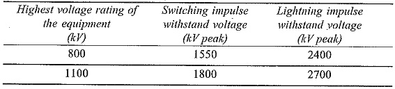
The rating of the impulse voltage generator was arrived at, based on the requirement of the insulation levels for external insulation of 800 kV and 1100 kV transmission systems. These are given below:
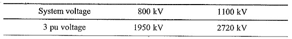
The generator was also intended to be used in long air gap breakdown studies for the optimization of conductor-to-tower and conductor to conductor air clearances in 800 kV and 1100 kV systems. For phase to phase air insulation clearance, considering 3 pu as the overvoltage between the phases, the switching impulse voltages required are:
Pollution Laboratory: The pollution performance of transmission line strings and other support insulators play a very important role in the determination of the adequacy of insulation for the transmission system. Salt fog test, which simulates the marine pollution and the solid layer test, which simulates the industrial pollution on the insulator are carried out in the pollution laboratory. The main test hall of this Operation of UHV Laboratory which is cylindrical in shape has an internal diameter of 24 m and a height of 27 m. The diameter of the hall was arrived at considering the maximum width of a 1100 kV transmission line V-string at the tower as 18 m. The height was decided on the consideration of a minimum ground to the bottom of the insulation chain clearance to be 12 m. All the metal structures in the Operation of UHV Laboratory were treated with anti-corrosive paint to withstand saline fog contamination. The salt fog is generated through two specially constructed nozzle systems as per the lEC 507 standard and the test voltage source is the outdoor cascade transformer having the short circuit power as required by the standards. An 850 kV wall bushing was used to lead the test voltage into the test hall from the outdoor transformer.
Measuring and Calibration Instruments: The Operation of UHV Laboratory is equipped with some of the best measuring and calibration instruments, such as the radio interference measuring system, partial discharge detector, experimental transmission line, corona loss meter, insulator surface pollution current integrator, FFT analyser, sound level meter, electric. and magnetic field meters, unit step voltage and current generators, recurrent surge generator, line conductor, vibration monitor, etc.
The research programmes undertaken at the Operation of UHV Laboratory since its commissioning in 1994 are given below. These programmes were undertaken based on the specific needs of the electrical utilities and the high voltage equipment manufacturers.
- theoretical and experimental studies of the corona performance, namely studies of the acceptable levels RI and AN generated, and studies on the electric fields under the transmission lines, methods of reducing them and studies on the interaction between the electric fields and biological systems,
- computational and experimental studies on the withstand capabilities and insulation coordination of long air gaps which form part of the transmission tower and equipment, when subjected to overvoltages having specified characteristics,
- experimental studies on the performance of various types of insulators in the Operation of UHV Laboratory as well as in natural surroundings, where conditions of weather and pollution vary continuously. Advancement of laboratory test techniques to simulate the above pollution conditions and to improve the insulator design for better performance are also being studied,
- experimental and computational studies on aeolian vibrations of conductor bundles and optimizing the conductor system. The economic impact of such studies are very significant. Further, evaluation of vibration performance of new conductor designs (self-damping, twisted, etc.) and the effectiveness of anti-vibration devices (dampers, spacer, spacer-dampers) are also being studied.
In addition to the research activities mentioned above, there has been considerable activity in the Operation of UHV Laboratory in type testing, proving tests and routine production testing. 800 kV insulator strings have been successfully tested for both lightning and switching impulse voltages in recent years. Further, considerable work has been done to determine the design parameters on the experimental transmission line. Considerable laboratory time has been devoted for mechanical testing as well as for impulse and power frequency testing,
High Voltage test facilities and large size high voltage laboratories are available at only a few places in the country and abroad as each of them costs several millions of dollars. It has been stated that a fully screened high voltage Operation of UHV Laboratory with all test and research facilities will cost US $10-50 million. In Table 11.6 details of a few large size high voltage laboratories in the world are listed along with the ratings of the equipment available. Some of the laboratories like those at the Indian Institute of Science, Bangalore, Central Power Research Institute, Bangalore, and Hyderabad have research facilities available apart from the normal test facilities.