Frequency Compensation Methods:
Phase-Lag and Phase-Lead Compensation – Lag compensation and lead compensation are two Frequency Compensation Methods often employed to stabilize op-amp circuits. The phase-lag network in Fig. 15-7(a) introduces additional phase lag at some low frequency where the op-amp phase shift is still so small that additional phase lag has no effect. It can be shown that at frequencies where XC1 ≫ R2, the voltage v2 lags v1 by as much as 90°. At higher frequencies where XC1 ≪ R2 no significant phase lag occurs, and the lag network merely introduces some attenuation. The effect of this attenuation is that the Av/f graph is moved to the left, as illustrated in Fig. 15-7(b). Thus, the frequency (fx1) at which AvB = 1 [for a given closed-loop gain (ACL)] is moved to a lower frequency (fx2), as shown. Because fx2 is less than fx1, the phase shift at fx2 is less than that at fx1, and the circuit is likely to be stable.
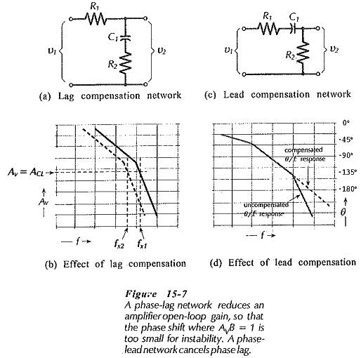
The network in Fig 15-7(c) introduces a phase lead. In this network, when XC1 ≫ R1, the voltage v2 leads v1. This phase lead cancels some of the unwanted phase lag in the operational amplifier θ/f graph, [see Fig. 15-7(d)], thus rendering the circuit more stable. Phase-lag and phase-lead networks are both used internally to Frequency Compensation Methods op-amp circuits. Both types of circuit can also be used externally.
Manufacturer’s Recommended Compensation:
Most currently-available operational amplifiers contain internal compensating components, and do not require additional external components. Some have internal compensating resistors, and need only a capacitor connected externally to complete a compensating network. For those that require Frequency Compensation Methods, IC manufacturers list recommended component values and connection methods on the op-amp data sheet. An example of this is illustrated in Fig. 15-8 for the LMI08.
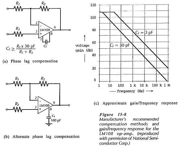
When selecting standard value compensating capacitors the next larger values should be used. This is termed over-compensation and it results in better amplifier stability, but, it also produces a smaller circuit bandwidth.
Miller Effect Compensation:
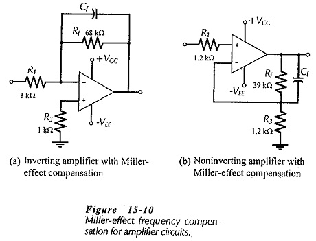
Miller effect involves connecting a capacitor between the output and input terminals of an inverting amplifier. Miller-effect compensation of an op-amp circuit is very simple, and it is often the only external method available for stabilizing a circuit where the op-amp is internally compensated. A capacitor (Cf) is connected across the feedback resistor, as shown in Fig. 15-10(a) and (b). The capacitor value is calculated to have an impedance equal the feedback resistor value at the desired signal cutoff frequency (f2).
![]()
This reduces the closed-loop by 3 dB at the selected frequency. So long as the op-amp is stable at this frequency, the circuit will not oscillate. The op-amp used should have an upper cutoff frequency much higher than f2.