Trigger Pulse Generator Circuit:
The Trigger Pulse Generator Circuit is activated by signals of a variety of shapes and amplitudes, which are converted to trigger pulses of uniform amplitude for the precision sweep operation. If the trigger level is set too low, the trigger generator will not operate. On the other hand, if the level is too high, the UJT may conduct for too long and part of the leading edge of the input signal may be lost.
The trigger selection is a 3-position switch, Internal-External-Line of trigger pulse generator circuit as shown in Fig. 7.12. The trigger input signal is applied to a voltage comparator whose reference level is set by the Trigger Level control on the CRO front panel.
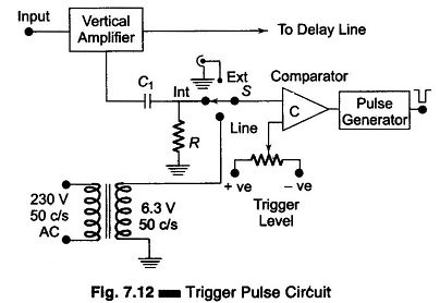
The comparator circuit C produces a change in the output whenever the trigger input exceeds the present trigger levels. The pulse generator that follows the comparator produces -ve trigger pulses each time the comparator output crosses its quiescent level, which in turn triggers the sweep generator to start the next sweep.
The trigger sweep generator contains the stability or sync control, which prevents the display from uttering or running on the screen. Stability is secured by proper adjustments of the sweep speed. Sweep speed is adjustable by means of a sweep rate control and its multiplier, i.e. range control. The timing resistance RT is used for sweep rate control and timing capacitor CT is changed in steps for sweep rate control.